Understanding Voltage Response Of An LC Circuit
Question submitted by Ashish Roy, Havells-Sylvania, India
For an undamped LC circuit excited by an AC voltage source through simple phaser equations, we come to see that the circuit becomes short circuited at the resonant frequency. However if we analyze the voltage gain across the capacitor we also see that the gain becomes infinite at the resonant frequency. I have doubts.
On one end we are saying that the voltage gain is infinite and also saying that the circuit is short circuited. Can we prove that the voltage on the capacitor accumulates to infinite voltage over a period of time? (Because it just seems unlikely that the voltage built up across the capacitor will suddenly be infinite within the first ac cycle of the supply voltage being turned on. I am assuming that the source is a sine voltage and at t=0,the voltage is also
Answer:
A simple LC circuit is shown in Fig. 1. The circuit is underdamped and the Q is controlled by R1, which can be in series with L1, in series with C2 or proportioned between the two. For simplicity, the circuit is normalized to a 1 Hz resonant frequency and a characteristic impedance of 1 Ω, defined by the equal values of L1 and C1.
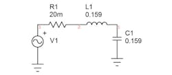
Figure 1
At resonance, the input resistance is 1/R1, so the Q is 3 as shown. At resonance the impedance of the capacitor is 1 Ω. Therefore, placing a 1 V peak sinewave at the resonant frequency results in 3 Apk and the voltage across the capacitor is 3 V pk. At a Q of 10 the resistance is 0.1 Ω and a 1 Vpk sinewave at the resonant frequency results in 3 A peak and the voltage across the capacitor is 3 V peak. Increasing the Q further to 50, the resistor is 20 mΩ and the current for a 1 V peak sinewave is 50 A peak resulting in 50 V across the capacitor. If the Q is infinite then the resistance is 0 and the current is infinite. The voltage across the capacitor is then infinity times the characteristic impedance (1 Ω) or infinity.
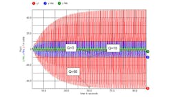
On the other hand, the time it takes for the circuit to build up to the full amplitude requires approximately Q cycles. The voltage across the capacitor for 3 values of Q is shown in Fig. 2.
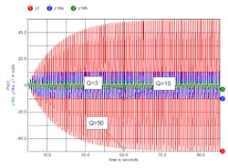
Figure 2
We are much more accustomed to seeing the response to a step input, which looks quite different as shown in Fig. 3. In this case the amplitudes are much lower and the response decays rather than increases with time.
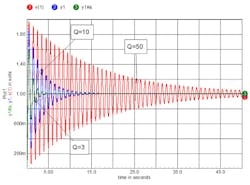
Figure 3
We can easily see both responses in a measurement of a resonant circuit both at and below resonance as shown in Fig. 4 and Fig. 5.
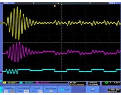
Figure 4
In this actual measurement a burst at the resonant frequency shows the very large response that grows with time while the low frequency step response shows a much smaller response and decaying with time.
The measurement below is just another example of the response to a step occurring both at resonance and also much below resonance.
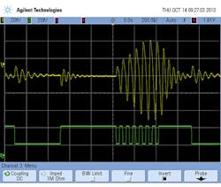
Figure 5
In Fig. 4, the amplitude at resonance is limited by the number of cycles in the burst. The Q of this resonant circuit is approximately seven, requiring approximately seven cycles to reach full amplitude. In this measurement the burst only contains four cycles in the burst. Fig. 5 includes seven cycles in the burst and so the amplitude is close to the maximum amplitude it will attain.
About the Author
Steve Sandler
Steve Sandler is the founder and chief engineer of AEi Systems LLC and the president of Picotest. At Picotest he is responsible for signal injector product development, as well as the overall operation of the test equipment company.
Comment About the Article
To join the conversation, and become an exclusive member of Electronic Design, create an account today!

Leaders relevant to this article: