Power Semiconductor ATE System
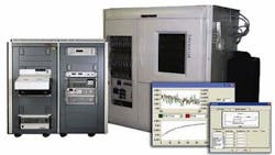
The Interpro SemTest HT consists of a temperature chamber rated at 60 to 225°C, +/-2°C and associated hardware rack that provides the test hardware. Internal racks are included to mount the DUT carrier cards and internal temperature is maintained with LN2 cooling. The equipment rack consists of a Card Cage Assembly installed in the rear wall of the Temperature Chamber. The rear wall contains 10 slots that align with the FSD Module connectors. The combination of the Card Cage Assembly and Temperature Chamber will make up a Chamber Assembly. The Chamber Assembly requires support from a System Cabinet that houses the system power supplies, measurement electronics, PC Controller, and the PowerStar control and operational software.
The heart of the system is the Force/Sense DUT (FSD) Module. The FSD module is a 6 U euro-card format that has a front panel control/monitor interface and a rear connector where the DUT Carrier Card will mount. Each FSD module controls up to 8 DUT Test Cells. The FSD Module provides local force, sense and control signals for HTRB and HTGB testing. Each DUT can be individually controlled by the FSD Module. As each FSD Module houses 8 DUTs, a total of 10 FSD Modules will be required for a single SemTest HT80 system. The system may be expanded in blocks of 80 DUT to 160, 240, 320 etc.
The system continuously monitors the current flow in each DUT. If at any time the current exceeds the set limit, the supply voltage to this the device is turned off to prevent damage. All other DUTs continue to be tested.
The system also has the ability to reverse the polarity of the high voltage supply automatically as part of a test routine without having to turn the tester off and change jump leads.
Tests and measurements include voltage up to 1200 V, current up to 1000 A, power up to 20 kW (total dissipated power), a range of DUT Voltages and a temperature range from -40 °C to +180 °C. System test configuration is programmed at a PC using a user friendly GUI (Graphical User Interface). Local control of the test is performed by distributed local controllers. A DUT interface card is used to provide high power isolated control for particular DUT types. Test results are written to an SQL Database for analysis and traceability.
DUT failures are detected by real time DUT monitoring circuitry, which compares measured values to warning and control limits based on DUT history. When a DUT starts to fail, all electrical stresses are removed within 30 msec. This prevents further catastrophic damage to the DUT and allows the user to remove it for detailed failure mode analysis.b
