Power Analyzer Optimizes Power Conversion System Designs
You can characterize test instrumentation for power conversion systems as a classic case of “necessity is the mother of invention.” As power conversion systems have grown in importance it became necessary to develop test instruments devoted to their unique power testing requirements. This led to the introduction of the power analyzer as a single instrument for testing power-oriented circuits in a power conversion system.
Related Articles
- Power Analyzer Has Easy-to-Use Display
- Power Analyzer Measures Narrowband, Full Spectrum and Harmonics Simultaneously
- Power Device Analyzer for Power Circuit Design
- Precision Multi-Phase Power Analyzer
- Three-Phase Power Quality Analyzer Travels Anywhere
Although, there is no generally accepted definition for a power analyzer, it can be considered as an instrument that enables a power conversion system design engineer to make all required ac and dc measurements that will ensure proper operation of the associated power circuits. To understand power analyzer capabilities, we have to look at their key operational characteristics.
As an important first step, the power analyzer should measure DUT (device under test) power consumption and energy efficiency to determine if the design meets product goals. As the efficiency of the DUT increases, the accuracy of a power analysis measurement must increase or it will be difficult to determine if small power losses are attributable to the power lost in high-efficiency conversion or measurement error. Therefore, the power analyzer must provide adequate measurement accuracy, particularly at low power levels.
This file type includes high resolution graphics and schematics when applicable.
Determining a product’s power quality is also an important power analyzer function. For example, designers need to verify the product's power factor. An energy-consuming device with a low power factor draws more current than a device with a power factor near 1.0. Higher currents require the power distribution system to have higher capacity that increases infrastructure costs and wastes energy. Plus, some regulations mandate manufacturers to build power-consuming devices with high (near unity) power factor.
Low power factor can also be caused by high harmonic current content, which creates issues in multiphase power distribution systems where odd harmonics produce excessive current in the power circuit's neutral line. A power analyzer can aid the design of products with low power factor by measuring the power factor and harmonic content to verify their product's performance.
Solar panel systems also require attention to power analysis measurements. The power coming out of the associated inverter must be clean and free from noise, have low harmonic content and be well regulated to avoid polluting the grid. To ensure that the inverter output meets these criteria, engineers can use a power analyzer to measure frequency, power factor, phase angle (between the sinusoidal AC voltage and current), real or active power (watts), apparent power (volt-amperes), reactive power (VAR) and harmonic content (typically to the 40th or 50th harmonic).
Besides measuring the steady-state power characteristics of their DUTs, design engineers must check its functional performance. Functional testing tends to be dynamic testing, where some test condition is momentarily changed while observing the DUT's behavior. One example is checking the inrush current. Many devices draw a large amount of current for a short duration when power is first applied. These inrush currents can be many times larger than the steady-state operating current, so it is important to measure them to ensure proper sizing of fuses, circuit breakers and wiring. Another example is transient testing, where the designer disrupts the input power momentarily to determine whether the DUT output remains operational and within specifications.
An additional dynamic measurement task for the power analyzer is to monitor the output waveform for the main power switch in a switch-mode power supply. Measurement of the rise and fall times of the power switch allows the designer to determine switching losses. The faster the rise and fall times the lower the switching losses and the more efficient the circuit. In addition, any ringing or switching transients on the power switch output waveform could indicate EMI generation by the power conversion system.
A single power analyzer with the necessary capability can perform all the power circuit tests in a power conversion system. However, power analyzer capability varies from manufacturer to manufacturer. As a minimum, the power analyzer should make all required ac and dc power measurements and produce analyzed results to ensure that the product:
· Complies with all local, regional and international standards
· Meets its established functional goals
· Meets reliability goals
· Operates efficiently
· Behaves properly under transient conditions
· Minimizes generation of EMI
· Minimizes power line harmonics
Enhanced capability of power analyzers allows them to replace oscilloscopes as the instrument of choice for testing power conversion system power circuits. Power Analyzers offer higher accuracy and easier connection to the DUT, making them ideal for steady-state measurements of power consumption, efficiency and power quality. For these measurements, the accuracy of the power analyzer gives design engineers higher measurement integrity than an oscilloscope. With floating inputs and direct-current measurement, power analyzers make it easier for designers to connect to their DUTs. Some power analyzers offer adequate measurement accuracy, but they can sometimes be cumbersome to use and can lack the ability to characterize power consumption under dynamic conditions.
Recent power analyzers have also assumed some of the oscilloscope’s ability for the single-shot measurement necessary for dynamic measurements in functional tests. Compared to oscilloscopes, these power analyzers provide more accurate efficiency measurements for power conversion systems. Plus, analyzers can have floating, isolated front ends with compatible probes for floating and current measurements. In contrast, oscilloscope probes reduce measurement accuracy and make it harder to connect to the DUT for power-related measurements.
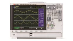
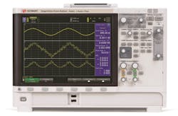
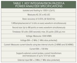
Responding to the need for an instrument better suited to testing power circuits in power conversion systems, Keysight introduced the IntegraVision power analyzer (Fig. 1). It combines accurate power measurements and touch-driven oscilloscope visualization capability in a single instrument. Table 1 lists the key specifications of this Power Analyzer.
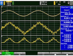
The Keysight IntegraVision power analyzer simplifies the task of testing power conversion system power circuits to access dynamic views of current, voltage and power so designers can see, measure and prove the performance of their designs (Fig. 2). IntegraVision power analyzers enable designers to quickly and interactively measure AC and DC power consumption, power conversion efficiency, operational response to stimulus and common AC power parameters such as frequency, phase, power factor and harmonics - all with 0.05% basic accuracy,16-bit resolution and single-shot measurement capability. This power analyzer allows designers to characterize power consumption under steady-state and highly dynamic conditions with 5-M samples per second digitizing speed and 2-MHz bandwidth.
The IntegraVision power analyzer allows designers to address multiple test scenarios with the flexibility of wide-ranging, isolated inputs up to 1,000 VRMS (Cat II). The instruments offer external sensor inputs and 2-ARMS and 50-ARMS direct current inputs, standard on all channels. The external sensor input supports current probes and transducers up to 10-V full scale.
Shipment of the single-phase IntegraVision measurement system (PA2201A) is scheduled for mid-2015, followed by a three-phase version (PA2203A) toward the end of 2015. The single-phase measurement system case already has space allocated for the components used in the three-phase power analyzer, so the overall case size will be the same for both instruments.
Among other manufacturers who call their test instruments “Power Analyzers” are Tektronix, and Xitron in the U.S., Yokogawa (Japan), and Newtons-4th Ltd (U.K.). These instruments vary in capability and price.
About the Author

Sam Davis
Sam Davis was the editor-in-chief of Power Electronics Technology magazine and website that is now part of Electronic Design. He has 18 years experience in electronic engineering design and management, six years in public relations and 25 years as a trade press editor. He holds a BSEE from Case-Western Reserve University, and did graduate work at the same school and UCLA. Sam was the editor for PCIM, the predecessor to Power Electronics Technology, from 1984 to 2004. His engineering experience includes circuit and system design for Litton Systems, Bunker-Ramo, Rocketdyne, and Clevite Corporation.. Design tasks included analog circuits, display systems, power supplies, underwater ordnance systems, and test systems. He also served as a program manager for a Litton Systems Navy program.
Sam is the author of Computer Data Displays, a book published by Prentice-Hall in the U.S. and Japan in 1969. He is also a recipient of the Jesse Neal Award for trade press editorial excellence, and has one patent for naval ship construction that simplifies electronic system integration.
You can also check out his Power Electronics blog.


