Reduce Reactive Grid Currents with Ripple Current Steering Filtering
A follow-up to the article “Design a PFC Resonant Coupled Inductor That Doesn’t Distort Power Factor” (July 2015) described the design of the resonant inductor. This article describes how “off-the-shelf SMD components” can be used with the normal PFC inductor for Ripple Current Steering Filtering and allows wide bandwidth operation and freedom from large X caps (capacitors) across the input ac line.
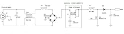
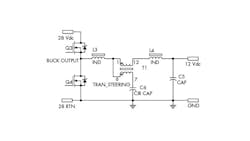
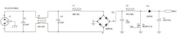
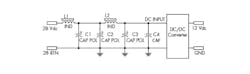
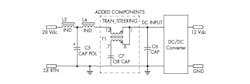
Figure 1 shows a PFC Input schematic with the normal configuration at the top. Figure 2 shows the component changes needed to convert to Ripple Current Steering Filtering. X caps, C2, 4 at the top can have a total capacity of 3.0 uF and will draw large amounts of reactive grid current, increasing with voltage and frequency. The bottom section shows how these X caps have been replaced with C7, a smaller typ. 100nF, needed for reducing high-frequency noise getting back to the grid. It will also reduce incoming noise spikes.
L8 (Fig. 2) is the normal PFC inductor and a small SDM transformer, T1, is inserted between L8 and the input filter. T1’s primary inductance is in the order of a few µH and L8 is >100µH so there is low voltage across T1 primary and its E*T (< 100V*µS) allowing a very small transformer or coupled inductor to be used for separating the PFC inductor current into its two components. My setup used a very small common mode choke, rated at 5.0A (#ACM7060-301 7.0mm x 6.0mm) to act as the steering transformer. The coupling between primary and secondary is not important. (K>0.90 is adequate). C9 will circulate all the high-frequency switching noise to ground and will have the half wave rectified ac voltage across it. A low ESR polypropylene cap should be used. T1 secondary is a low impedance to the switching frequency, steering switching currents into it to ground. The low-frequency currents that flow through the primary must see an inductance, L6 to block high frequencies.
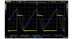
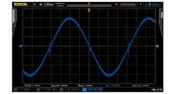
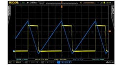
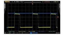
Looking at the waveform pic, the PFC inductor current contains two components (Fig.3). A line-frequency component shown expanded to the switching frequency (Fig. 4) that flows to the input filter and an triangular switching frequency (Fig. 5) with no dc component that flows through the circulating cap C9. Figure 6 is the squeaky clean ac input current.
This configuration is best suited for separating high- and low-frequency current components. The most common instance is the PFC inductor and the worst case, with a ripple factor of 2.0, is the CrCM. Its frequency varies about 4:1. A Resonant Coupled Inductor, as seen in my previous article, would have a difficult time with the variable frequency. This configuration is not resonant in the operating frequency range so it operates wide bandwidth an easily yields 40 dB of attenuation over the frequency of operation. If the ripple frequency is fixed, then an inductor can be added in series with C9 and a smaller C9, sized to resonate with it. The larger either C9 or L6 become, the higher will be the noise attenuation. A stepped-up turns ratio can be used in the steering transformer for added attenuation and C9 sizing.
I took a 250W PFC demo board, ST-EVL6563S-250W (AN3119 from STMicroelectronics). Its input filter does not contain a DM inductor so I inserted one (#WE-7447709101, 100uH 12mm, 12mm, 10mm) between C4 and L2-3. A common-mode inductor primary (#ACM7060-301 7.0mm x 6.0mm) was inserted between the new 100uH inductor and L2-3. This CM inductor was used as a 1:1 transformer. The secondary was completed with a 330nF cap to ground. The input AC current was completed through a LISN and monitored as shown in the pics. I removed C1- 470nF first, then C2-1.0uF then reduced C4- 1.5uF to 330nF. With each cap removal or reduction, the circulating noise current increased, reducing the input noise current. The circulating noise current was 40dB greater than the input noise current. The power factor improved to 0.9997. The steering transformer/inductor had little heat rise. This unit is rated 264 Vac and 60 Hz. The total X cap value was 3.0uF which at 60 HZ = 883 Ohms. At 265Vac, that is 0.30Arms of reactive current and 80 W of reactive power. This configuration would also be helpful in an avionics environment where the power form is of 400 Hz to 800 Hz operation.

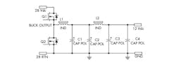
The other schematics of Ripple Steering Filtering, (Figs. 7, 8, 9, 10) used on input or output power supplies, should be self-explanatory. Contact the author of this article at [email protected].

About the Author
Harry Dellamano
Consultant
Comment About the Article
To join the conversation, and become an exclusive member of Electronic Design, create an account today!

Leaders relevant to this article: