Solar System Efficiency: Maximum Power Point Tracking is Key

One of a solar engineer’s tasks is to determine the efficiency of a solar panel system. A first step in determining solar system efficiency is a review of solar panel system technology. A PV panel system consists of an array of PV panels whose output is applied to an inverter that converts the panel’s DC output to AC. These inverters must ensure they can convert maximum power from the PV panels to which they are connected. Maximum PV panel power depends on the panels themselves as well as environmental factors of temperature and solar irradiation.
To continuously obtain maximum power from PV panels means that, despite environmental effects, you have to operate at their maximum power point (MPP). To accomplish this, inverters used with PV panels employ maximum power point tracking (MPPT), which is their key to optimum solar system efficiency. Therefore, one way to check PV panel-inverter efficiency requires a method for monitoring the inverter’s MPPT under all environmental conditions—that is, for temperature and solar irradiation changes, which is challenging. Also, you need to ensure your solar inverters are capable of converting the maximum power available from the solar array.
There are three ways to test the PV panel-inverter:
- Apply direct sunlight to the PV panel connected to an inverter
- Expose the PV panel-inverter combination to a bright light source that duplicates sunlight.
- Apply the output from a PV simulator to the inverter.
MPPT algorithms are complex, and under-the-sun testing with a comprehensive set of temperature and irradiance conditions is difficult, expensive, and time consuming. Comprehensive under-the-sun testing on a variety of solar modules is nearly impossible because solar cell technologies change quickly. Plus, you also have to provide a means for monitoring the inverter’s MPPT.
One type of light source activated solar simulator uses a 100-W Xenon arc lamp with optimized optical system that delivers more than one AM1.5G sun irradiance over a 50 × 50 mm area. Standard optics minimize harmful ultraviolet radiation. Optional accessories include an electronic shutter to provide computer control for light soaking and timed irradiance. This approach also needs to provide a means for monitoring the inverter’s MPPT.
A PV simulator relies on the model of an ideal solar cell with a current source (I1) in anti-parallel with a diode (D) (Fig. 1). When the cell is exposed to light it generates a direct current that varies linearly with solar radiation. In addition, there is a resistance in parallel with the diode (RP) and another in series (RS).
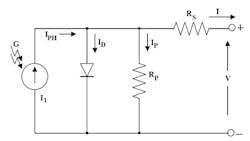
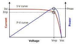
Photovoltaic (PV) panels have a nonlinear voltage-current characteristic based on the model in Fig. 1. The I-V curve ranges from the short circuit current (ISC) at zero volts to zero current at the open circuit voltage (VOC). At the knee of a normal I-V curve is the maximum power point, where the panel produces its maximum electrical power. The associated inverter must constantly adjust the load, seeking the specific point on the I-V curve that produces maximum DC power.
Using this simplified model of the PV cell, you can produce an I-V (current-voltage) curve of a PV cell that describes its energy conversion capability under existing conditions of irradiance (light level) and temperature (Fig. 2). The curve represents the combinations of current and voltage at which the string could be operated or “loaded”, with constant irradiance and cell temperature. Figure 2 shows a typical I-V curve and power-voltage or P-V curve derived from the PV cell model. Pmax is the maximum power point. Imp is the current and Vmp is the voltage at the maximum power point.
PV array simulators aid the development and verification of inverter maximum power point tracking algorithms and circuits. Small increments in power production have a dramatic effect on the profitability of solar power generation. PV array simulators help engineers capture as much energy as possible from their inverters, which improves the economics of solar power generation.
To perform an accurate test of solar array inverters, the output of a PV simulator must faithfully follow the I-V curve of a solar array. It must respond just as a solar array would to the changing load conditions imposed by the inverter under test. To evaluate how well a simulator can do this, you need to consider three parameters: output noise current, phase error between output voltage and current, and the MPP tracking accuracy.
There is essentially zero phase difference between the output voltage and output current of a solar panel or array, even when inverters use MPP tracking strategies that change the load very quickly. To accurately simulate a solar panel or array, therefore, it is important that the phase error of the simulator be less than 15 deg., even if the load is changing quickly.
Another important specification is the maximum power point dynamic tracking accuracy. This is a measure of how much a simulator will deviate from a programmed I-V curve under dynamic conditions.
As inverter power classes increase in power, the size of your test array becomes unmanageable. Examples of PV simulators are the recently introduced Keysight N8937APV and 8957APV (Fig. 3).
You can use the N8937/57APV photovoltaic array (PV) simulators in a laboratory or on a manufacturing line to simulate the output characteristics of a real-world photovoltaic array. The N8937/57APV PV array simulators are single-output, programmable DC power sources that can quickly simulate I-V curve characteristics under different environmental conditions (temperature, irradiance, age, cell technology, and more), enabling engineers to quickly and comprehensively test their inverters.
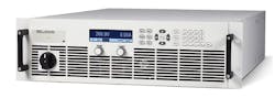
These PV array simulators provide stable output power, built-in voltage and current measurements and autoranging output voltage and current from 500 to 1,500 V and 10 to 30 A. The autoranging capability makes the units more flexible than traditional rectangular-output power supplies, given that they expand the power curve to provide more voltage and current combinations.
The PV simulator does not provide an output related to the MPPT. It puts out power of a known curve, which has a max power point, since every curve has a max power point. Since the user creates the curve and downloads it into the PV simulator, the user knows the max power point that the simulator applies to the inverter. The user also knows the power into the inverter. Measuring the power out of the inverter then allows the user to calculate efficiency. However, measuring the input power and the output power at the same time also gives this same efficiency, and that is what the power analyzer does.
Besides using the N8937/57APV units to simulate PV arrays, engineers can use them for other test and measurement tasks. They provide 15-kW autoranging, programmable DC power for design verification, and ATE applications that require just the right amount of performance at an affordable price. Engineers can easily configure multiple units in parallel to create a single power supply that offers more than 90 kW.
This PV array simulator allows you to:
- Develop and verify the performance of inverter peak power tracking algorithms and circuits.
- Measure inverter power conversion efficiency over a variety of simulated conditions (varying temperature and irradiance).
- Verify the ability of the inverter to produce grid level power from low to high voltage extremes.
- Perform qualification tests – confirm inverter performance during or after exposure to varying environmental conditions.
- Perform accelerated lifecycle tests.
- Perform certification tests.
About the Author

Sam Davis
Sam Davis was the editor-in-chief of Power Electronics Technology magazine and website that is now part of Electronic Design. He has 18 years experience in electronic engineering design and management, six years in public relations and 25 years as a trade press editor. He holds a BSEE from Case-Western Reserve University, and did graduate work at the same school and UCLA. Sam was the editor for PCIM, the predecessor to Power Electronics Technology, from 1984 to 2004. His engineering experience includes circuit and system design for Litton Systems, Bunker-Ramo, Rocketdyne, and Clevite Corporation.. Design tasks included analog circuits, display systems, power supplies, underwater ordnance systems, and test systems. He also served as a program manager for a Litton Systems Navy program.
Sam is the author of Computer Data Displays, a book published by Prentice-Hall in the U.S. and Japan in 1969. He is also a recipient of the Jesse Neal Award for trade press editorial excellence, and has one patent for naval ship construction that simplifies electronic system integration.
You can also check out his Power Electronics blog.
Comment About the Article
To join the conversation, and become an exclusive member of Electronic Design, create an account today!

Leaders relevant to this article: