5 Current-Sensing Resistors
Although there are several ways to sense current flowing from a source such as a battery, or to a load such as a motor, the current-sense resistor is among the most widely used approaches. There are several reasons for this: reasonable cost, electrical compatibility with the rest of the circuit, and the ease of scaling and adjusting the sensing arrangement.
The basic principle is simple and based on Ohm’s Law: Insert a resistor of known value in series with the current flow, measure the voltage across that resistor, and do a simple I = V/R assessment, which can be accomplished with all-analog circuitry or via computation. This is often called a shunt resistor, but that’s somewhat of a misnomer, since the resistor doesn’t “shunt” anything.
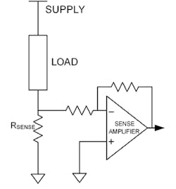
The first question is: Should the sense resistor be inserted on the high side or the low side of the source or load? For various reasons, it’s almost always placed in the high side. In the low-side arrangement (Fig. 1), one terminal of the resistor is connected to the circuit common (generally called “ground” although this, too, is a misnomer in many cases).
While this makes it easier to sense the resistor voltage, it also means that the load is no longer connected to ground, which leads to system stability and performance issues. It also can’t be used with non-grounded loads such as motor in a H-bridge drive configuration.
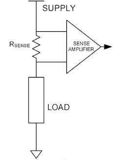
The alternative is inserting the resistor on the high side, with neither end grounded (Fig. 2). As a result, the voltage-sensing circuit at the resistor can’t be a simple grounded amplifier. Instead, it must be a differential or instrumentation amplifier, and many ICs are available for this function.
This amplifier must have a common-mode voltage (CMV) rating that’s greater than the common-mode voltage at the resistor. In some special cases, or where the CMV at the resistor is high (typically greater than 50 to 60 V), it may be technically prudent or even required to use galvanic isolation between the resistor and the rest of the circuit to maintain signal integrity and assure user safety. This isolation can be achieved via magnetic, optical, or capacitive techniques. Again, these are easy-to-use components.
Resistor Essentials
Once the high-side/low-side decision is made, and the resistor interface circuit is determined, the designer must focus on the resistor itself. Although it’s conceptually a simple component (“it’s just a resistor” is often heard), several critical questions must be addressed:
- What is the “optimum” resistor ohm value?
- What is the resulting dissipation of the resistor and thus its required wattage rating?
- What is the temperature coefficient of resistance (TCR or tempco) of the chosen resistor, and how does it affect resistor value and thus accuracy of the reading? TCR is usually expressed in ppm/°C, or ohms change per degree per initial resistance.
- How will the interface circuitry physically connect to this resistor to maintain accuracy of reading? The solder or other joint between the sense resistor and the wire leads will have its own TCR and drift, which may be significant compared to the readings.
Sizing the resistor is a tradeoff decision. On one side, the resistor value should be larger so that the voltage drop across it is also large, and, in turn, will have wider dynamic range and higher SNR. On the other side, a large resistor and its associated voltage drop will decrease the voltage available to the load, waste power via I2R loss, and have detrimental self-heating.
There’s no single best answer to this tradeoff, but most designs size the resistor so that the voltage drop at maximum current is 100 mV, which seems to be a good compromise in many situations. As a result, the resistor is often less than 1 Ω and may even be smaller, down into the milliohm and even sub-milliohm range.
Once the resistor value is set, the associated power dissipation and self-heating temperature rise, and this tempco-related drift can be calculated. The selected resistor must have a wattage rating commensurate with the power dissipation, of course, and a tempco that’s low enough whereby associated drift doesn’t affect the reading accuracy beyond an acceptable limit.
Tempco and drift are often critical sense-resistor parameters. For example, the resistance of a 50-Ω precision resistor with a fairly small TCR of just 20 ppm/°C will not change more than 0.000020 Ω per ohm per °C change. In contrast, pure copper has a TCR of about 4000 ppm/ppm/°C; a standard resistor has a TCR of about several hundred ppm/°C. Ultra-stable resistors are available with TCRs in the low tens and even single-digit ppm/°C.
Another factor is the inductive nature of the resistor. If the current being sensed is dc or low frequency, this may not matter. However, the current’s frequency increases into the tens of kilohertz and higher. Resistor self-inductance will affect the overall circuit dynamics and performance. As a result, current-sense resistors are available in styles ranging from wirewound designs that are somewhat inductive to special film designs with very low inductance.
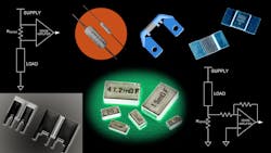
Dozens of vendors offer resistors specifically designed for current sensing, with thousands of models and variations spanning a wide range of resistances, power ratings, type of construction, connection options, and other specifications. Here are five representative current-sense resistors:
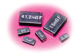
The SL07 series from KOA Speer Electronics Inc. is a surface-mount device available in 5- to 100-mΩ values. The smallest unit is rated for 0.75 W and measures 5 × 2.5 × 1.7 mm.
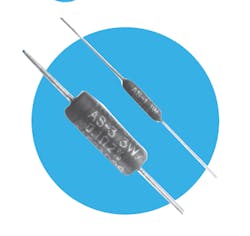
The (N)AS Series of semi-precision, power-wirewound resistors from TT Electronics, with TCR ±20 ppm/°C, is available from 0.1 Ω to 175 kΩ, 0.25 to 10 W, and in both inductive and non-inductive versions.
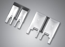
The Type SR precision current-sense resistors from Caddock Electronics Inc. feature a non-inductive design with a compact footprint that minimizes circuit board space, Kelvin (four-wire) terminals, and resistance values from 0.005 to 1.00 Ω.
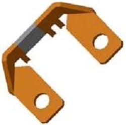
The Vishay Dale WSMS5515 series with a 4-terminal (Kelvin) connection design and very low inductance (< 0.5 nH) is available from 0.1 to 0.5 mΩ.
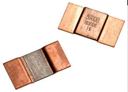
The LRMAP5930 0.2-mΩ current-sense resistor from TT Electronics handles up to 200 A and can dissipate 15 W. It measures 15 × 7.75 × 1.4 mm, and the special alloy construction features a TCR of ±100 ppm/°C.
