Modern Efficiency is Powered by Digital Flexibility
The efficiency requirements of power supplies have been evolving quickly in recent decades and now differ greatly from what was conventionally taught in textbooks. High efficiency at a certain rated condition is only the first step—a fully qualified and competitive power supply design must achieve high efficiency across the whole operating range.
The most popular efficiency-related regulations and agencies—such as Energy Star, 80 PLUS, EISA by U.S. Department of Energy, and the European Commission’s ErP and CoC—all have clear but different requirements across a wide operating range, typically from 10% to 100% load, as well as no-load condition.
At the same time, different applications also have various specifications at certain operating conditions based on the practical application demands. For example, PC power supplies may have particular efficiency specifications at a certain load condition below 10% of the rated power, depending on the sleep-mode power consumption of each brand and each model.
TV power supplies care most about the efficiency at standby mode, usually at 300-mW input power, which is the upper limit of the power consumption when the TV is turned off by remote. Adapters typically have the strictest requirement on no-load power, even occasionally below 10 mW, because most often adapters work without any load plugged in. With so many different specifications, there’s no way to cover all of them with a unified design, even for the same rated power.
Furthermore, any attempt on efficiency optimization inevitably has systematic influence on ripple, transient response, and audible noise, which are also very essential performance parameters. As a result, today’s fully qualified and competitive power-supply products always need tremendous work on the design adjustment, parameter fine-tuning, and tradeoffs.
Evolving PFC
As the most popular topology combination for power-supply designs, power factor correction (PFC) with LLC (two inductors and one capacitor) has been commonly used for decades, by way of conventional analog control schemes. However, with new trends and growing efficiency requirements, today’s design solutions must be much more flexible to effectively support all kinds of system needs.
The PFC stage can benefit significantly from a multimode control scheme other than the conventional options of simple critical conduction mode (CrM) or continuous conduction mode (CCM). CCM operation at heavy-load conditions is able to minimize the peak current, reducing the size of the inductor and EMI filter (Fig. 1).
Under medium-load conditions, a hybrid of CCM and discontinuous conduction mode (DCM) or CrM is able to create a balance between peak current amplitude and switching loss. Complete DCM or burst operation in light-load conditions lead to the best light-load efficiency by minimizing the switching loss. Therefore, a multimode control scheme with programmable switching frequency and a transition point for each operation mode helps fine-tune the efficiency performance curve.
On the LLC stage, the market is moving from relying on conventional voltage-control mode to current-control mode, which can offer better stability and transient response. In other words, new designs based on current-control mode allow for much more room for the loop adjustment amidst a range of application demands.
Multimode LLC Control
Similarly, the LLC control scheme is also developing multimode approaches. For example, Figure 2 shows three different operation modes targeting efficiency and other performance optimizations for different load conditions. Under heavy-load conditions, the resonant mode achieves optimum efficiency with guaranteed zero-voltage switching and minimal RMS current.
In skip mode, a switch-idle period is implemented every couple of switching cycles. This reduces the switching loss and magnetic loss, while keeping the envelope frequency above the audible noise range. As the load reduces further, it can go into burst-mode operation to minimize the switching loss.
In addition, a number of settings can be adjusted in burst operation, such as the envelope frequency limitation and soft on/off. All of these techniques can be adopted to help a solution meet all requirements for efficiency, ripple, and audible noise. A solution that offers these features with programmable operating points and entry/exit thresholds would be well-suited for modern power-supply designs.
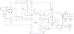
For example, MPS’s second generation of digital PFC and LLC combo controllers, the HR121x family, maintains features and flexibility that help with today’s power-supply design (Fig. 3). Designing a power supply with an HR121x part makes it possible for users to meet different efficiency requirements. The HR121x family combines the features of both analog and digital ICs, and is optimized for PFC and LLC applications.
By integrating a high-voltage current source, an X capacitor discharge with safety certification, and a low-side driver for PFC and half-bridge driver for LLC, the external circuits remain simple and clean (Fig. 3, again). The fast-response feature of analog circuits is retained, too—all of the delay-sensitive functional blocks are still implemented by analog and mixed-signal design on the chip. As a result, the HR121x can achieve cycle-by-cycle current limitation, capacitive-mode protection, and dead-time adaptive adjusting just like an analog controller.
Flexibility Factor
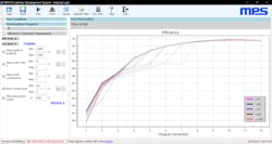
On the other hand, the digital core and the multiple-time-programmable (MTP) memory implemented on the chip help boost flexibility for the given solution. The key parameters, switching characteristics at critical points, and transition thresholds among different operation modes can be programmed through a UART-based dongle and the user-friendly GUI (Fig. 4). In this way, it provides the flexibility to meet different efficiency requirements from a variety of applications, power ratings, and performance requirements.
Moreover, the programmability of the HR121x can be leveraged to a next level of usage, accelerating the whole R&D progress by automatically searching for the most optimized digital code. Through the UART communication, the part can be linked to automatic-test-equipment systems.
By sweeping targeted registers with defined ranges and steps, all test results for efficiency, ripple, power factor, etc. can be derived. Then, screening across the test data determines the most optimized code combinations. This work can be done automatically, minimizing labor resources. Moreover, the judgement is made by real tested data, which is the most objective way to determine the best code design.
Figure 5 illustrates a LabVIEW-based automatic test system with the HR121x. In the demonstration, the PFC and LLC control-mode-related registers are swept, and all test results are collected as the total database. Then the top five are filtered out based on the recommendation of the most optimized digital code for the highest average efficiency.
Similarly, the same database can be used to derive the most optimized digital code for the highest efficiency at certain load conditions, power factors above a certain specification, an output ripple below a certain specification, or any combination of these parameters.
Therefore, it might be time to move to solutions like the HR121x that not only offer cutting-edge control schemes, but also provide the digital flexibility to be able to adapt and meet targets for a number of applications and operating conditions.
Siran Wang is Technical Marketing and Application Engineering Manager at Monolithic Power Systems.


