
Download this article in PDF format.
As process geometries for FPGA, DSP, ASIC, and high-performance processors continue to shrink, power-rail voltage-accuracy requirements get tighter and tighter. Core voltages now typically fall in the 0.9-V range, and core currents are tens of amperes. In addition, FPGAs and other devices often require multiple (2 to 4) supplies. On top of that, some devices require these supplies to be turned on in a specific sequence.
While these requirements are difficult, the real problem may be the fact that the supply voltages must be held to within a 1% to 3% range to meet the device’s demands. Achieving 1% accuracy is a real design challenge. However, with the right components, you can design a supply that will deliver a better than 1% output voltage accuracy over the full temperature range.
Sponsored Resources:
- Achieve better than 1% accuracy when powering FPGA core rails
- Managing thermals in high-current, high ambient-temperature applications
- 4-phase, 160A reference design for communications equipment
Contemporary Power Requirements
Any modern piece of equipment using FPGAs, or any high-performance processor, is going to need a power supply with low voltage, high current, and tight voltage regulation. Data-center rack servers and switches, large medical test systems, and military communications equipment are representatives of such needs.
A modern LTE or 5G wireless base station is another good example. The environment is one of high temperature, where the equipment requires a significant output current from point-of-load dc-dc regulators without the luxury of air flow to keep the devices cool.
To meet those tough requirements, most designers would develop a large complex supply with conservative specifications even when other solutions are available. However, it’s hoped that power-supply engineers will discover a better solution here.
Such a solution is Texas Instruments’ TPS546D24A. This new dc-dc buck converter offers high-end thermal performance and can produce a full 40-A output at 85°C. It will help lead to smaller, simpler designs that deliver 1% output accuracy.
A Highly Qualified IC
If you’re designing high-current supplies for tough environments, you should become familiar with the TPS546D24A. The 5- × 7-mm QFN device can take an input from 2.95 to 16 V and generate an output in the range of 0.6 to 5.5 V. Output current capability is up to 40 A. This switching converter can operate at frequencies in the 225-kHz to 1.5-MHz range selectable in 12 steps. Furthermore, better than 1% accuracy is possible when powering FPGA core rails or other high-current chips.
A key feature of this sophisticated chip is a full PMBus interface. (Recall, the PMBus is a variant of the popular I2C interface that connects multiple slave devices on a common drop bus and operates at a nominal 1 Mb/s.) The PMBus allows you to configure the device and monitor critical parameters such as output voltage, output current, temperature, and several others. Fault monitoring is an additional desirable feature.
A Best-in-Class Capability
A unique stackable capability allows four units of the TPS546D24A to be placed in parallel to provide 160 A of output current (see figure). Two, three, or four devices may be stacked or connected in parallel as shown to obtain such current capability.
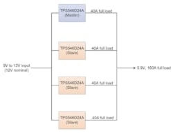
This four-IC circuit is the configuration used in Texas Instruments’ reference design TIDT090A, as described in Test Report PMP21814. In this reference design, all TPS546D24A units operate at a switching frequency of 650 kHz with a PMBus interface that’s used to configure key converter parameters like internal compensation. Efficiency, thermal, stability, and load-transient test results are included.
Sponsored Resources: