EMI in Wireless Power Transfer Designs
This article is part of the TechXchange: Delving into EMI, EMC and Noise
Members can download this article in PDF format.
What you'll learn:
- Mitigating EMI in apps that use magnetic resonance.
- How to reduce EMI when using WPT in UAVs and other drones.
- Dealing with electric-vehicle EMI and its impact on those with pacemakers.
- Shielding in electric trains.
Wireless power transfer (WPT) technology, an excellent technology for easier and safer battery charging, doesn’t use a wired electrical contact that can cause an unwanted electric spark or even deliver dangerous electric current to users. When transferring power from a source to a battery or other load, strong electromagnetic fields (EMFs) will be generated. The vehicle power inverter charger output will have a wide range of harmonics.
Designers are tasked with reducing the electromagnetic fields (EMFs) and electromagnetic interference (EMI) in WPT systems. What follows are some methods that will help designers create a robust and safe WPT design while minimizing EMI.
Magnetic-Resonance Method
WPT architectures that use a magnetic-resonance method between coils are employed for safety, wide distances, and high-power capabilities. This kind of system is perfect for electric vehicles, defense applications, and medical equipment. Advantages include high power-conversion efficiency, ability of fault tolerance, and wide operating capability even with coil misalignment.
One drawback when applying this method of wireless transfer is that the coil shielding materials will induce high capacitive parasitics in a wireless-charger application. This will generate EMI from the wireless charger, which may affect user safety as well as possible malfunction in nearby circuitry.
Reducing EMI in the aforementioned application can be achieved with the use of spread-spectrum techniques (SST) with no additional cost to the system design. This methodology reduces the peak and quasi-peak levels of EMI via the spreading of the bandwidth of the power converter. It will reduce the number and size of the EMI filter, leading to a lower volume in the overall power converter.
However, there’s an added cost in using this technique: An increase in power-converter voltage ripple due to the need to change the operating points of the power converter either randomly or periodically. Reference 1 uses a bridgeless rectifier, at the secondary side of the WPT, which will control the output voltage without an additional dc-dc converter at the secondary side. This ripple can be reduced in other ways, too (see Reference 2 and Reference 3).
Reducing EMI in WPT for UAV/Drone Charging
WPT technology is a safe and convenient method to charge batteries, since it’s unaffected by any external conditions. While charging batteries, there’s always a possibility of unintended electrical sparks or dangerous currents to users. During the transfer of power from a source to a battery, there may be powerful EMFs and EMI generated. A power inverter will most likely have a wide range of harmonics that increase EMI.
This method also can be applied to unmanned aerial vehicles (UAVs)/drones, whose usage and applications are growing exponentially in number.
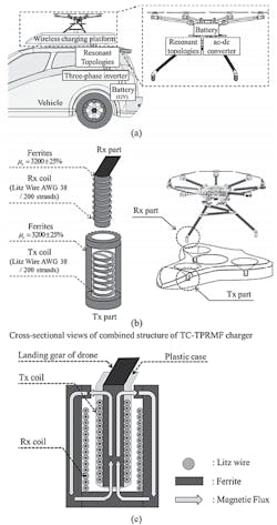
Reference 4 explains the design of a tightly coupled, three-phase resonant magnetic field (TC-TPRMF) charger for drones with low EMF and EMI. This design consists of a three-phase inverter, resonant matching circuit, wireless charging platform, ac-dc converter, and drone battery that uses the guided magnetic flux in resonance (GMFIR) structure (Fig. 1).
EMI Risk in Pacemakers
EMI can be dangerous for people with pacemakers and implantable cardioverter defibrillators (ICDs) who are outside of an electric vehicle (EV) while it’s charging. This is caused by coil currents of WPT systems that can generate large, time-varying magnetic fields in the surrounding environment.
It’s been shown that the most severe fields will not be inside the vehicle cabin, but rather in the side areas close to the ground outside the EV. Vehicle power-supply devices must be compliant with EMF safety standards for human exposure as well as be electromagnetically compatible with ICDs and pacemakers.
The standard for automotive applications of WPT systems requires that at the operational frequency, f = 85 kHz, the magnetic flux density will need to be below B = 27 μT, to not exceed the reference levels of ICNIRP 2010 guidelines. And it must be lower than B = 188 μT (150 A/m) so as not interfere with the normal sensing operation of the pacemaker with unipolar leads. The induced peak-to-peak voltage, in the loop area formed by the unipolar pacing lead, will need to be lower than V p-p = 510 mV as well.
An active shielding coil can be designed to reduce the risk for patients with pacemakers or similar devices. It’s produced by a time-varying magnetic field generated via 85-kHz WPT coil currents. The design of the ferrite shield above the secondary coil (Fig. 2) will reduce the field on both external lateral sides of the EV without reducing the electrical performance of the WPT system. In addition, each side of the ground pad has an active coil with the shape of a partial annular sector that’s placed around the circular primary coil.
EMI Shielding in Electric Train WPT
WPT is being used in EVs, electric buses, and even in electric trains. In these high-power application cases, the systems have many existing electrical components, such as signal and control systems, which are directly responsible for human safety. EMI can wreak havoc on these safety systems in the presence of strong WPT fields that are powering electric trains, for example.
The power inverter in a WPT transmitter is usually the main source of EMI. To minimize the EMI in the power converter, focus must turn to the main source causing it—the switching transistor in the power inverter. The switching action of the power transistors generate harmonic components into the air that may affect nearby systems, such as electric train safety systems like crossing gates and safety signals for the trains.
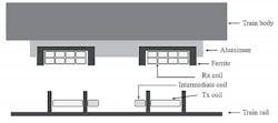
Reference 9 suggests an intermediate coil, consisting of Litz wire and a lumped tuning capacitor, within the Transmit (Tx) coil to help reduce third harmonics causing radiated EMI (Fig. 3).
Reference 9 also shows that the intermediate coil generates the same phase as the magnetic field at operating frequency. Furthermore, the intermediate coil generates the opposite phase of the magnetic field at the third harmonic frequency. Utilizing this theoretical principal, the intermediate coil is designed to suppress the third-harmonic components without reducing system efficiency.
Summary
Wireless power transfer is a technology that easily transfers power, from a source to a load, over the air without using wires. It improves safety with added convenience for users.
This article has suggested multiple scenarios discussing some various uses of WPT. There’s also a drawback in using WPT due to the generation of EMI. The good outweighs the bad here, since we can minimize that EMI in various ways. There’s no doubt that wireless power will find new and useful applications in the future, and designers can expect that more novel ways will emerge to minimize the radiated EMI from this WPT method.
Read more articles like this at the TechXchange: Delving into EMI, EMC and Noise
References
1. “Wireless Power Transfer System with Reduced EMI Emission Employing Spread Spectrum Technique,” 2020 IEEE PELS Workshop on Emerging Technologies: Wireless Power Transfer (WoW) November 15-19, 2020, Seoul, Korea.
2. “Spread Spectrum Technique to Reduce EMI Emission for an LLC Resonant Converter Using a Hybrid Modulation Method,” IEEE Transactions on Power Electronics, vol. 33, no. 5, pp. 3717-3721, May 2018.
3 “Spread Spectrum Technique for Decreasing EM Noise in High-Frequency APWM HB Resonant Converter With Reduced EMI Filter Size,” IEEE Transactions on Power Electronics, vol. 34, no. 11, pp. 10845-10855, Nov. 2019.
4. “EMI Reduction Methods in Wireless Power Transfer System for Drone Electrical Charger using Tightly-coupled Three-phase Resonant Magnetic Field,” IEEE Transaction on Industrial Electronics, 2017.
5. “Wireless Charging in Electric Vehicles: EMI/EMC Risk Mitigation in Pacemakers by Active Coils,” 2019 IEEE PELS Workshop on Emerging Technologies: Wireless Power Transfer (WoW).
6. “SAE TIR J2954, Wireless Power Transfer for Light-Duty Plug-In/Electric Vehicles and Alignment Methodology,” SAE International, 2016.
7. ANSI/AAMI/ISO 14117:2012 – “Active implantable medical devices. Electromagnetic compatibility. EMC test protocols for implantable cardiac pacemakers, implantable cardioverter defibrillators and cardiac resynchronization device.”
8. International Commission on Non-Ionizing Radiation Protection, “Guidelines for limiting exposure to time-varying electric and magnetic fields for low frequencies (1 Hz - 100 kHz),” Health Phys., vol. 99, pp. 818-836, 2010.
9. “Design and Analysis of EMI Shielding Method using Intermediate Coil for Train WPT System,” IEEE 2018.


