Members can download this article in PDF format.
At one time, designing products with motors was relatively easy. Brushed dc motors and single-phase ac induction motors didn’t require a lot of extra hardware—and no software—to design a product.
Today, though, these motors are mostly being replaced with brushless dc (BLDC) motors. They’re much more sophisticated, efficient, and quiet, but do require a great deal of design knowledge and effort, including software development. Now, your ability to design BLDC products just got easier thanks to an integrated circuit that lets you achieve all of the benefits offered by these motors.
Benefits of BLDC Designs
Perhaps the most desired benefit of BLDC motors is their increased power efficiency over older designs. Today, government regulators require new electrical products to meet strict efficiency standards. In many cases, a BLDC motor design is your only choice.
Second, there’s the unexpected benefit of quiet operation. Motors are mechanical devices and do make noise. Despite that, quietness isn’t always one of the design goals. Using a BLDC motor helps to achieve that goal.
Other benefits include the use of low voltages—12 and 24 V; longer life; and the fact that they’re now available in larger sizes to tackle bigger products.
Applications
BLDC motors have assumed many of the jobs that older brushed dc motors and some ac motors once reigned over. Some examples, which may be similar to your project, include robotic vacuums, fans, pumps, washers, air purifiers and humidifiers, and multiple automotive devices.
Motor Control
A BLDC motor works like most other motors in that its rotation is produced by the interaction of two magnetic fields, one fixed and the other movable. Typically, multiple stator coils are embedded around the periphery of the BLDC motor assembly. The stator coils are usually wired into three groups, making it a three-phase motor. A rotor consisting of multiple permanent magnets rides and rotates inside the stator coils. Then a sequence of pulses is applied to the stator coils.
The occurrence of the pulses must be timed so that they interact with the permanent magnets. The control circuitry driving the stator coils get their correct timing from sensors that indicate the rotor’s orientation. BLDC motors typically use several sensors like Hall-effect devices to produce signals that are used by the controller to keep the stator-coil magnetic fields moving.
Other control approaches and algorithms are available, such as a sensorless method that uses the back electromotive force (back-EMF) induced into the stator coils by the rotating rotor magnets. These signals are sent to the controller that generates the three-phase pulses applied to the stator coils.
One emerging control technique is field-oriented control (FOC). FOC is a sensorless method that reads the trapezoidal-shaped feedback voltages from the motor stator windings and then processes that feedback into control signals for the motor. The motor stator windings are driven by three MOSFET half-bridges.
For some designs, you could use a pre-programmed and packaged BLDC motor-control module, which may be satisfactory for certain common applications. However, many if not most products will require a custom design. This is a challenge because a special hardware controller/driver is needed, along with the programming to make it work. And testing and tuning the BLDC requires considerable time. However, one new option is to select and adopt an integrated-circuit driver that will save you from that task.
It’s All in the Driver
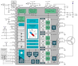
Texas Instruments offers a single-chip BLDC motor-control chip that takes the agony out of the BLDC control process. Known as the MCF8316A, it’s a three-phase, code-free sensorless FOC controller/driver that’s preprogrammed for the FOC control algorithm. As a result, all you need to do is give the device some speed, direction, and torque inputs and the IC does the rest. No external MCU is required for full operation. The internal algorithm is configurable with internal register settings. The figure shows a detailed block diagram of the device.
This device was designed for use with 12- and 24-V motors. Its dc supply range is 4.5 to 35 V, and output-current capability is 8 A peak. The outputs to the motor winding are derived from the three integrated MOSFET half-bridges. The MOSFETs have a low 95-mΩ on-resistance. Output current-sense resistors are built-in.
Some other features include:
- Configurable EEPROM to store device configuration.
- Multiple protection circuits for both the motor and the IC, including overvoltage and undervoltage, overcurrent, and thermal conditions, among others.
- Internal LDO and buck regulators to power the internal circuits and some external circuits.
- I2C interface for inputs and diagnostics output.
- Spread-spectrum and slew-rate adjustment to help mitigate EMI.
- Housed in a 40-pin VQFN 5- × 7-mm package.

