What’s the Difference Between MOV Technologies for Circuit Protection?
What you’ll learn:
- Basics of MOV and GDT device construction and operation.
- Typical surge rating densities, leakage current, and capacitance of compared devices.
- Commonly experienced aging mechanisms and failure modes.
Design engineers tend to be hyper-focused on the function of their designs, making sure the design meets product functionality specifications. The continuing trend is that basically every new design comes with budgetary and as well as size constraints, which makes achieving a successful design that much more challenging.
These goals many times can cause design-for-reliability to take a back seat and details like circuit protection are often be left to the very end of the design cycle. To help meet schedule requirements, many designers will simply copy previous design circuit-protection solutions and hope for the best in the qualification testing.
That approach, unfortunately, may lead to unpleasant surprises because each design cycle implements a new generation of electronic components. And, as applications evolve to meet smaller and faster (and lower cost) requirements, they can be more susceptible to damage during the electrical surge qualification testing. On top of that, budgetary pressures often force designers to specify component voltage ratings with a minimum of design margin.
Failures of surge-protection devices or the downstream components they’re supposed to protect can surface during compliance testing, or worse, out in the field where warranty costs and a company’s reputation may be at stake. Fortunately, recent innovations in metal oxide varistor (MOV) and gas discharge tube (GDT) technologies have brought forth a wider range of ceramic-based overvoltage circuit-protection products.
These new solutions offer tradeoffs between cost, size, capability, and performance. Some of the recent advances address the issues of the aging mechanisms in standard MOV devices to help ensure that the circuit-protection element itself doesn’t become a reliability issue.
This article describes the evolution of various MOV and GDT devices generally available in the market. It looks at construction, surge-rating density, leakage current, capacitance, aging mechanisms, and failure modes. While no design engineer seeks to increase the budget for circuit protection, design engineers may gain an appreciation for the enhanced surge-protection performance and space savings delivered from newer designs that may justify specifying a more premium circuit-protection product.
Conventional MOV Technology
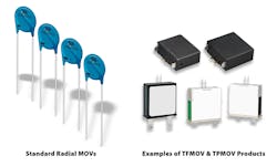
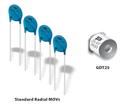
Standard radial leaded MOVs typically consist of a doped zinc-oxide disc metallized on both sides and leads attached with an epoxy coating over the disc portion. With billions of such MOVs sold globally each year, they clearly have been proven as a workable solution for many designs.
The downside, though, is that conventional MOVs are known to age due to factors such as repeated surge events, constant exposure to the ac line, heat, and humidity. Over time, conventional MOVs are known to develop leakage current. This current warms the MOV and speeds the aging process. Such an issue can develop into a thermal-runaway condition that would eventually cause the MOV to catch on fire.
To protect against this failure mode, designers have learned to specify MOVs with voltage ratings well above the intended operating voltage. They also may use MOVs with higher surge ratings. The thickness of an MOV disc is generally proportional to the breakdown voltage, and the area of an MOV disc is generally proportional to the surge rating.
These MOVs with higher ratings are larger and generally more expensive, and they’re typically only specified in equipment that requires a longer life. One other major downside is that higher-voltage-rated MOVs let higher peak voltages through to the downstream circuitry, requiring those components to have higher voltage ratings. This puts even more pressure on the circuit expense budget.
Despite these drawbacks, MOV devices remain the primary choice for low-cost consumer electronics and applications where cost is the primary driver, reflecting their relatively short life expectancy and generally high commoditization.
Thermal Overload Protection
Some types of equipment must pass regulatory testing (such as UL 1449) designed to force the MOVs into thermal runaway without the device being set on fire. This is where thermal fuse MOV (TFMOV) devices are typically used.
TFMOV devices are constructed with a series thermal fuse to disconnect the MOV from the line when the disc temperature rises above a preset level. However, many of the standards for this kind of testing use current-limited power supplies that may not simulate real-world circumstances. With full AC power available, the TFMOV thermal fuse may or may not successfully open the circuit.
A more sophisticated design known as a thermally protected MOV (TPMOV) device is known to offer greater thermal protection than TFMOVs. This is due to their construction, which has an internal moving mechanism that provides a much more positive action, ensuring a complete disconnect of the MOV from the power line.
Both TFMOV and TPMOV devices can include an indicator function that enables an enunciator circuit to alert the system that the MOV is now offline and is no longer protecting the downstream circuitry. It should be noted that these devices do nothing to prevent MOV failure - they simply disconnect the failing MOV and alert the system that there is no longer protection on the failed line. Until a technician can replace the failed device, the system is vulnerable to further surge events.
Historically, these thermally operated devices (Fig. 1) are most often deployed in systems where MOV degradation is anticipated and the MOVs are regularly replaced by technicians.
Series GDT Enhancement
Understanding the additional circuit-protection advantages, savvy designers will place a GDT in series with the MOV (Fig. 2). The GDT acts as a voltage-controlled switch that disconnects the MOV from the ac line until a significant surge event occurs. The GDT has the ability to switch on in less than a microsecond; the MOV will absorb the excess energy of the surge. Once the event has passed, the MOV will starve the GDT of current, thereby resetting it to its off state.
This arrangement has been shown to extend the life expectancy of the MOV significantly. That’s because it’s not experiencing constant voltage stress and insignificant switching transients, which are the major factors causing the MOV to age.
Designers can specify discrete MOV and GDT devices, or they may opt for an integrated solution such as the Bourns GMOV protection device (Fig. 3). One advantage of this type of integrated solution is that it provides a production-line-friendly option of using a conventional MOV or a GMOV device without jumpers or PCB changes.
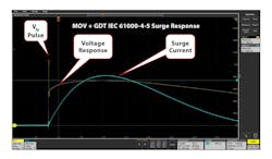
An important consideration when using all series GDT solutions is that they will exhibit a short voltage spike let-through to downstream circuitry while the GDT is switching on. The “front protection voltage pulse” (Vfp) of a GMOV device (Fig. 4) lasts only about 300 ns, and, hence, contains very little energy. Often, the first components downstream are rectifiers and filter capacitors. In these types of circuits, the capacitors typically have no problem absorbing the pulse.
Besides preventing the leakage current and thermal runaway of the MOV, adding a series GDT also creates tolerance of temporary-overvoltage (TOV) events. In addition, series MOV and GDT solutions are considered good choices for long-life applications where field failures under normal operating exposures are unacceptable.
Enhanced Geometry MOV Technology
MOV devices also can fail catastrophically if they experience repeated surges beyond their ratings. As stated earlier, designers often specify larger MOV devices with higher surge ratings to avoid these failures, at a disadvantage of higher cost and increased size. All of these failures resulted in a burned spot at the perimeter of the MOV. This can be predicted by careful computer modeling of MOV operations. There’s a build-up of an electric field at the device’s edge and, once the surge begins, the current is concentrated at that point until there’s a failure.
This failure mode can be mitigated by constructing a thicker edge on the MOV disc. Thickening the edge region results in the edge of the MOV having a higher breakdown voltage. In addition, the breakdown point is effectively forced into the interior area of the MOV, which enhances current sharing.
The technology utilized in Bourns EdgMOV devices is depicted in the computer modeling shown in Figure 5. It reveals that the maximum temperature of an EdgMOV disc will rise only about half as much as a conventional MOV. Thus, the EdgMOV disc can handle about twice the surge current of a conventional MOV disc of the same voltage rating and diameter, which has been confirmed through empirical testing by the company.
EdgMOV technology can be of real benefit in designs that are cost-sensitive and where PCB density is a leading concern.
Hybrid Protectors: Combining Integrated GDT and EdgMOV Technologies
Bourns recently introduced new protection devices that combine the integrated GDT function with its EdgMOV technology. Its IsoMOV™ hybrid protectors offer an efficient design that allows designers to do away with larger, generally lower-performing, and often more expensive surge-protection alternatives.
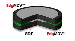
The IsoMOV devices are designed with two EdgMOV devices sealed together using an insulating glass to create a GDT chamber between them. Each EdgMOV disc provides half of the desired voltage rating and operates by ensuring that the current entering one lead must first pass through one EdgMOV disc. The current then passes through the GDT formed in the center of the two EdgMOV discs and back out through the second EdgMOV disc.
Formed in this way, the IsoMOV device has the functionality of both a discrete MOV and an MOV/GDT series combination in a package that’s barely thicker than a simple MOV of the same voltage rating. The IsoMOV disc area is about half that of comparable surge-rated MOV devices.
The market for some equipment designs will always demand the lowest-cost solution without consideration for operational life, reliability, and uptime application risks. Other markets will require equipment to be as robust as is technically feasible. There’s a suitable MOV technology and strategy for nearly every application. With the many surge-protection devices available, designers are equipped to make the best choice for their application specifications, operational requirements, and budgetary goals.
