Debugging and Optimization of a USB4 Logical Layer Link
What you’ll learn:
- What is USB4?
- Using the Lane Adapter State Machine to describe the behavior of the logical link layer.
- Step-by-step procedure for debugging and optimizing the USB link.
The USB Type-C connector has seen significant adoption with ubiquitous standards like USB, DP, and Thunderbolt. USB4, the latest variant of USB, will transmit and receive on all four lanes of the Type-C connector in parallel, with bonded rates of 40 Gb/s in each direction, for an 80-Gb/s link.
In USB 3.2, the link optimization is performed directly on the high-speed TX/RX lanes; the SBU (sideband use) lines aren’t utilized. In USB4, the link training is set up via the SBTX and SBRX wires. This article will prepare you to debug and optimize a USB4 logical layer link.
Before a USB4 link can even start, there are many steps that precede it. VBUS must be present, and the USB-PD protocol must agree that the link partners and the cable can run at the USB4 rate.
The USB4 physical data rate is 20 Gb/s on one lane and required to run in x2 mode for a 40-Gb/s bonded effective bit rate. Numerous other high-speed standards run much faster. The challenge with USB4 is that the link is required to work with a low-cost cable running as a 20 Gb/s x4 pipe or 80 Gb/s.
Putting It All Together
Now that we understand the various signals required, we must figure out the different solutions required to access, capture, and analyze the signals.
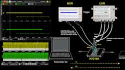
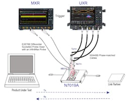
Figure 1 provides an overview of the different components:
- The N7019A provides access to all Type-C signals: VBUS, CC for USB-PD, SBTX/SBRX, and the high-speed TX/RX lines.
- The MXR-series oscilloscope has a real-time protocol trigger to capture the event of interest on the SBTX/SBRX lines.
- The UXR-series oscilloscope captures the high-speed 20-Gb/s signaling and performs protocol analysis.
Stepping Through the Logical Link Layer
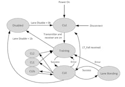
The Lane Adapter State Machine (Fig. 2) describes the behavior of the logical layer during the linkup sequence. Here’s a step-by-step through each of these states and sub-states:
- Entry to CLd when the link partners are initially connected.
- Transition from CLd to Training sub-state.
- Training.Lock1 sub-state where TxFFE negotiation is performed.
- Lane Bonding transition from two Single-Lane Links into a Dual-Lane Link.
- Disconnect state.
Entry to CLd State
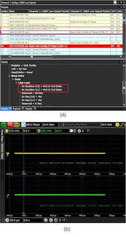
When a USB4 device under test (DUT) is powered on, it enters the CLd state.
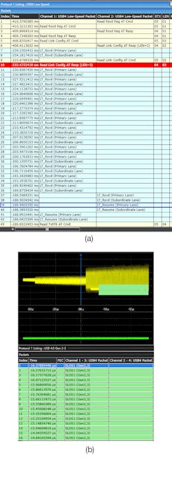
By decoding the Sideband channel SBTX/SBRX “Read Link Config AT” packet, you can read that the DUT is in the Cld state (Fig. 3a). In this state, the high-speed Tx and RX lanes are inactive (Fig. 3b).
Transition from CLd State to Training.LOCK1 Sub-State (Primary Lane)
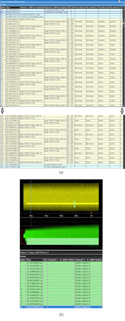
After exiting the CLd state, a Lane Adapter shall transition to the Training.LOCK1 sub-state. In this state, Symbols are synchronized, and Lane parameters are transferred between the ends on the lane. The high-speed TX and RX lanes are active in this state. This can be identified on the SBTX/SBRX lines channels by triggering on the “LT_Resume (Primary Lane)” packet (Fig. 4a).
On the high-speed TX/RX lanes, you will now see the back-to-back Symbol Lock Ordered Set/SLOS1 (Fig. 4b). The SLOS1 is a PRBS11 pattern with a high number of transitions to facilitate bit lock.
Transition from CLd State to Training.LOCK1 Sub-State (Secondary/Subordinate Lane)
Although Single Lane operation is an allowed fall-back position, USB4 DUTs are required to be run and tested in x2 mode. As a result, training and optimization of the secondary lane is required as well.
In Figure 5a, the trigger occurs on LT_Resume of Subordinate Lane. Notice that in Figure 5b, the lane common-mode voltage isn’t maintained.
Training.Lock1 TxFFE Negotiation State
Training.Lock1 state is also where the critical TxFFE settings are negotiated. This state continues until RxLocked(L0) and Rxlocked(L1) is complete.
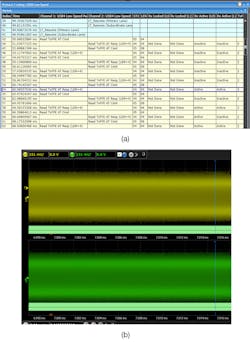
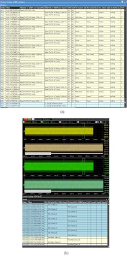
To capture this critical event, we need to trigger on the Rx Active packet (Fig. 6a). During this state, the USB4 high-speed lanes will be sending the high transition density SLOS1 (Fig. 6b).
Completion of TxFFE Negotiation
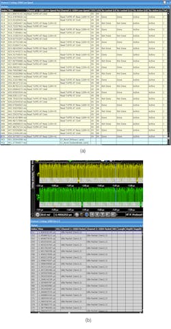
In this state, Rx Locked(L0) and Rx locked(L1) is set to 1b(done) in the Rx status word of the TxFFE register and the RxReqest bit is set to 0b (Fig. 7a). In addition, the Transport Layer will ensure the high-speed lanes have a continuous stream of Idle Packets (Fig. 7b).
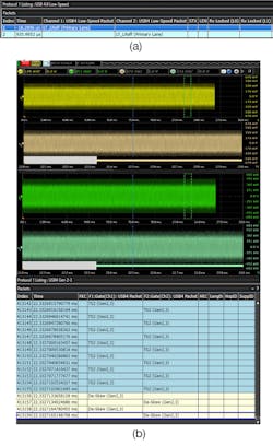
Lane Bonding (Two Single-Lane Links to Dual-Lane Link)
To ensure both lanes have proper skew, the de-skew Ordered Set shall be the first bytes sent after the TS2 Ordered Sets. TS2 Ordered Sets shall be transmitted on an Adapter in CL0 state until the de-skew Ordered Set is sent.
After completion of TxFFE on both lanes, Rx Locked (L1) is set to “Done” (Fig. 8a). In Figure 8b, you can see the transition on the high-speed lanes from TS2 Ordered Sets to the De-Skew Ordered sets.
Disconnect/System Sleep State
When a link partner is disconnected, it’s important to ensure the DUT goes into the System Sleep State by sending the LT_LRoff Transaction (Fig. 9). The high-speed lanes are also inactive in this state.
Summary
The USB4 Link is very complex due to the 20-Gb/s signaling rate, crosstalk from three other lanes also running at 20 Gb/s, the need to bond for an aggregate 40 Gb/s, and the need to be optimized over a lossy passive cable.
This article demonstrated the tools to debug and optimize your USB4 Logical Link by connecting to the DUT, triggering on the correct low-speed packet, capturing both the side-band and high-speed signals, decoding the signals, and viewing the time-correlated Analog waveforms to determine potential signal integrity issues in the link.
About the Author
Jit Lim
Strategic Planner, USB Type-C testing solutions, Keysight Technologies
Jit Lim has been enabling customers for over 34 years in test and measurement since graduating from MIT in 1986. He has published numerous technical papers and helped many worldwide customers characterize and validate their leading-edge designs. Today Jit Lim is the strategic planner for Keysight’s USB Type-C testing solutions.
Comment About the Article
To join the conversation, and become an exclusive member of Electronic Design, create an account today!

Leaders relevant to this article: