9 Different Types of Sensor Transmitters
Members can download this article in PDF format.
What you’ll learn:
- What’s the difference between a transmitter and a sensor?
- Nine different types of sensor transmitters.
- How does each type of transmitter work?
- What are the components of each transmitter type?
Sensors and transmitters have been playing an increasingly important role in the field of instruments and meters, and in industrial automation. These two instruments are commonly used on equipment that requires temperature, pressure, flow, and object-space measurements, and the results must be transmitted for further automation control.
Those unaccustomed with such instruments may easily get confused since both sensor and transmitter are used for medium measurement. So, to get started, let’s first talk about the differences between sensors and transmitters.
A sensor consists of a sensitive element and conversion element. The sensing element can sense the measured variables (temperature, pressure, liquid level, and flow), and the conversion element can convert the sensed variables into non-standard electrical signals or other forms of output signals. The output signal of a sensor is non-standard.
Different from sensors, a transmitter can’t sense the measured variables initially. Rather, it just converts the non-standard electrical signal outputted by the sensor into a measurable electric signal, usually in a 4- to 20-mA current signal, or 1- to ~5-V dc voltage signal. Meanwhile, a transmitter also amplifies the signal for subsequent receiving instrument.
At present, many transmitters are integrated with sensors to create one instrument. This integrated instrument is referred to as a transmitter, not a sensor; for example, the Rosemount transmitter 3051 series and ABB transmitter TTH 200 series, etc.
Below are 9 different types of transmitters in terms. Discussed are their work principles and components, to help better clarify what transmitter is the best option for a specific use.
1. Integrated Temperature Transmitter
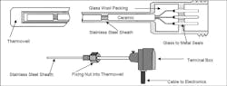
An integrated temperature transmitter is generally composed of a temperature probe (thermocouple or thermal-resistance sensor) and a two-wire solid-state electronic unit. When it’s manufactured, the temperature probe is directly installed in the junction box in a solid module to form an integrated transmitter.
There are essentially two types of integrated temperature transmitters:
Thermal-Resistance Temperature Transmitter
Work Principle
The thermal-resistance temperature transmitter integrates the temperature sensing element—the thermal resistance—and the signal-conversion and amplification unit to measure the temperature of liquid, steam, and other gas mediums or solid surfaces from −200 to 1600℃ in various processes. It’s usually used with a display instrument, recording instrument, and various control systems.
The temperature sensor is affected by the temperature to produce resistance or potential effect, which is converted to produce a differential voltage signal. After the thermal-resistance signal is converted and amplified, the nonlinear relationship between temperature and resistance is compensated by a linear circuit. After the V/I-conversion circuit, the transmitter will output a constant current signal of 4 ~ 20 mA corresponding to the measuring temperature.
Figure 1 shows the operation of a thermal resistance temperature transmitter.
Thermal-resistance temperature measurement is based on the principle that the resistance of the metal conductor increases with the rise in temperature. Most thermistors consist of pure metal materials. At present, platinum and copper are widely used, while nickel, manganese, and rhodium have been used to manufacture thermistors, too.
Components
-
Reference unit
-
R/V conversion unit
-
Linear circuit
-
Reverse-connection protection
-
Current-limiting protection
-
V/I-conversion unit
Thermocouple Temperature Transmitter
Work Principle
Figure 2 shows the work principle of a thermocouple temperature transmitter. The thermoelectric force produced by the thermocouple is compensated and amplified by the cold end. Then, the nonlinear error between thermoelectric force and temperature is eliminated by the linear circuit.
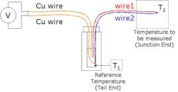
Next, the signal is amplified and converted into a standard 4 ~ 20-mA current output signal. Afterward, users can use the signal result in a microcomputer system or other conventional instruments. Or depending on the users’ requirements, the signal result also could be utilized for explosion-proof or fire-proof measuring instruments.
To prevent temperature control failure caused by thermocouple broken wire in thermocouple measurement, the transmitter is also equipped with power-off protection circuit.
When the thermocouple is broken or poorly connected, the transmitter will output the maximum value (28 mA) to cut off the instrument’s power supply.
Components
Reference source
Cold junction compensation
Amplification unit
Linearization processing
V/I conversion
Disconnection processing
Reverse-connection protection
Current-limiting protection
Other circuit units
The integrated temperature transmitter has a long list of advantages, including simple structure, lead savings, large output signal, strong anti-interference ability, good linearity, simple display instrument, anti-seismic and moisture-proof solid module, reverse-connection and current-limiting protection, and reliable operation.
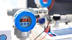
2. Pressure Transmitter
Pressure transmitters can convert the received gas, liquid, and other pressure signals into standard current and voltage signals. Then they send the results to subsequent instruments such as an indication alarm instrument, recorder, and regulator for measurement, indication, and process regulation.
Work Principle
A pressure transmitter is also called differential pressure transmitter. Its measuring principle is like that shown in Figure 3.
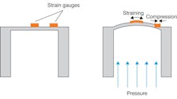
The process pressure and reference pressure act, respectively, on the two ends of the pressure-sensitive assembly of the integrated silicon, and the differential pressure makes the silicon wafer deform. The displacement of the deformation is extremely small (microns).
The full dynamic Wheatstone bridge on silicon wafer is driven by an external current source, and the output voltage is in the millivolt level, which is proportional to the pressure. Because of the excellent strength of silicon material, the linearity and variation index of the output signal are very high.
In operation, the transmitter converts the measured physical quantity into a voltage signal (mV). That’s sent to the differential amplifier with high magnification and can counteract the temperature drift.
Next, the amplified signal is transformed into the corresponding current signal by the voltage- and current-conversion unit. Via nonlinear correction, the standard current and voltage signal, which is linear with the input pressure, is generated.
The pressure transmitter can be divided into a general pressure transmitter (0.001 ~ 20 MPa) and micro differential pressure transmitter (0 ~ 30 kPa).
Components
-
Pressure sensor
-
Module circuit
-
Display meter
-
Case
-
Process connector
3. Liquid-Level Transmitter
A liquid-level transmitter is actually the application of a pressure transmitter in liquid-level measurement. According to the measuring method, installation method, and structure, it was later called a liquid-level transmitter, which also belongs to the scope of liquid level gauge. Three variations of this type of transmitter include:
Floating-Ball-Level Transmitter
Work Principle
Figure 4 depicts the work principle of a floating-ball-level transmitter.
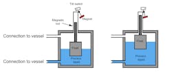
Generally, the specific gravity of a magnetic floating ball is less than 0.5, so that it can float on the liquid surface and move up and down along the measuring tube. The tube is equipped with a measuring component that can convert the measured liquid-level signal into a resistance signal proportional to the change of liquid level under the action of external magnetism. Upon completion of the measurement, the transmitter will convert the electronic unit into 4 ~ 20 mA or other standard signal output.
Designed with a module circuit, the floating-ball liquid-level transmitter has the advantages of acid resistance, moisture resistance, shock resistance, and corrosion resistance.
Constant-current-feedback and internal-protection circuits are integrated into the circuit, which can ensure the maximum output current not to exceed 28 mA. Therefore, the power supply can be reliably protected and the secondary instrument will not be damaged.
Components
-
Magnetic floating ball
-
Measuring catheter
-
Signal unit
-
Electronic unit
-
Junction box
-
Installation components
Floating-Buoy-Level Transmitter
Work Principle
Figure 5 shows the work principle of a float-buoy-level transmitter.
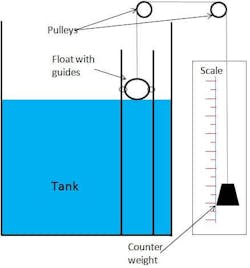
The buoy type of liquid-level transmitter is designed according to Archimedes the buoyancy principle, whereby the magnetic floating ball is changed to a buoy.
A float-buoy-level transmitter uses tiny metal-film strain-sensing technology to measure liquid level, boundary, or density. When used for measuring, it can operate according to the routine setting operation via control buttons on the work site.
The buoy is immersed in the liquid in the buoy chamber and rigidly connected with the torsion-tube system. The force on the torsion-tube system is the net value of the weight of the buoy itself minus the buoyancy on the buoy. Under the action of this resultant force, the torsion tube will twist at a certain angle.
The position, density, or boundary position of the liquid in the buoy chamber will change the buoyancy of the buoy immersed in the liquid, which will alter the angle of the twisted tube. The change is transmitted to the sensor rigidly connected with the torque tube, which changes the output voltage of the sensor. And the output signal will be further amplified by the electronic components and converted into 4 ~ 20mA current output.
The float-buoy liquid-level transmitter uses a microcontroller and related electronic circuits to measure process variables, provides current output, and has an LCD that displays the value. Its design employs HART communication capability.
Components
-
Detection part: buoy and connecting rod
-
Conversion part: lever, torque-tube assembly, sensor
-
Transmission part: CPU, ADC (analog-to-digital converter), DAC (digital-to-analog converter), and LCD display
Hydrostatic Pressure Transmitter
Work Principle
A hydrostatic-pressure-level transmitter is mainly used for liquid-level measurement in urban water supply and drainage, water-treatment plants, reservoirs, rivers, oceans, oil tanks, petroleum, chemical industry, electric power, and other applications.
The measured medium can be water, oil, acid, alkaline, and viscous liquid. The instrument can output a two-wire current signal at 4- ~ 20-mA dc, which has the advantages of advanced technology, high precision, stable and reliable quality, and easy installation and use.
The hydrostatic pressure transmitter is an ideal liquid-level measuring instrument for process detection and control systems.
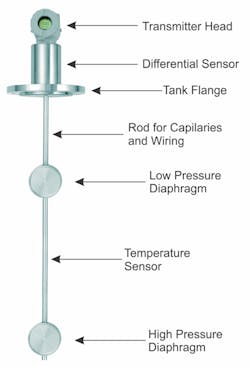
Figure 6 illustrates the work principle of a hydrostatic pressure transmitter. This transmitter is based on the principle that the hydrostatic pressure of the measured liquid is proportional to the liquid height.
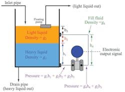
It uses the piezoresistive effect of diffused silicon or ceramic-sensitive elements to convert hydrostatic pressure into an electrical signal. After temperature compensation and linear correction, the electrical signal will be converted into a 4- ~20-mA dc standard current signal for output.
Installing and using a hydrostatic pressure level transmitter is very convenient. Users can put the sensor part of the transmitter directly into the liquid, and the transmitter part can be fixed with flanges or brackets.
Components
Trunk box
Sensor probe
Air conducting cable
4. Capacitance-Level Transmitter
A capacitance-level transmitter is suitable for industrial enterprises to measure and control the production process. It’s mainly used for long-distance and continuous measurement of the liquid level or powder solid level of conductive and non-conductive media.
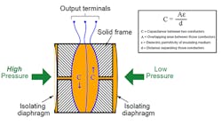
Work Principle
The work principle of a capacitance-level transmitter is shown in Figure 7. When two kinds of pressure from the measured medium enter the high- and low-pressure chambers of a capacitance liquid-level transmitter, they will act on both sides of the diaphragm of the δ element (i.e., the sensitive element). Next, by the diaphragm itself and the filling liquid, the signal will be transmitted to both sides of the measuring diaphragm.
When the pressure on both sides isn’t consistent, the displacement of the measuring diaphragm is proportional to the pressure difference. Thus, the capacitance on both sides isn’t equal. After oscillation and demodulation, it’s converted into a signal proportional to the pressure.
The ADC converts the current of the demodulator into a digital signal, whose value is used by the microprocessor to determine the input pressure value. The microprocessor controls the transmitter’s operation.
In addition, the microprocessor can carry out sensor linearization, reset measurement range, engineering unit conversion, damping, square root, sensor fine-tuning, and other operations, as well as diagnosis and digital communication.
At last, the DAC is able to fine-tune the corrected digital signal from the microprocessor into data, which can be corrected by the transmitter software. The data is stored in EEPROM, which will be perfectly safe even after a power failure.
Components
Capacitance Sensor
Reference source
Pulse width modulation
Conversion circuit
Constant current amplifier
Feedback unit
Current limiting unit
5. Ultrasonic Transmitter
An ultrasonic transmitter is divided into two categories: general ultrasonic transmitter (without meter) and integrated ultrasonic transmitter. The latter is more commonly used.
Work Principle
The ultrasonic-level transmitter can measure the material height in a container based on the principle of acoustic reflection. It measures and displays the material-level value (liquid level or material level) and sends the output signal to the host computer in the main control room.
Figure 8 shows the operational flow of an ultrasonic transmitter. It first measures the distance to the surface of the object, and the level value (liquid level or material level) is obtained by subtracting the distance measurement value from the installation height (the distance from the piezoelectric transducer’s surface to the bottom of the container).
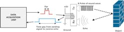
Therefore, the installation height must be set to the level meter. Other parameters will need to be set, too, such as the full scale and zero point of the remote current signal.
Ultrasonic transmitters are widely used in the water and sewage treatment field, such as in the pump house, collecting well, biochemical reaction tank, and sedimentation tank; electric power and mining industries, such as in slurry and coal slurry tanks as well as water treatment; and the petroleum industry.
They can be used to measure liquid level, material level, open channel, and other measurements of flowing liquid, as well as distance.
This type of transmitter solves many problems associated with traditional measurement methods (such as rotary, pressure, capacitance, and float types of transmitters), including sticking, winding, blocking, leakage, medium corrosion, and inconvenient maintenance.
Components
Piezoelectric chip
Ultrasonic probe
6. Antimony Electrode Acidity Transmitter
An antimony electrode acidity transmitter, an industrial online analytical instrument, provides functions such as PH detection, automatic cleaning, and electric signal conversion. It’s a PH measurement system composed of an antimony electrode and reference electrode.
Work Principle
Figure 9 illustrates four types of antimony electrode acidity transmitters and their components.
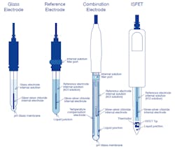
In an acid solution to be measured, a potential difference exists between the metal antimony surface and antimony trioxide due to the formation of an antimony trioxide oxide layer on the surface of the antimony electrode. The magnitude of the potential difference depends on the concentration of antimony oxide, which corresponds to the moderate concentration of hydrogen ion in the acid solution.
If we assume the moderation of antimony, antimony trioxide, and aqueous solution is 1, the electrode potential can be calculated using the Nernst formula.
Components
Acidity sensor
24-V ac power supply
Transmitter circuit
7. Acid, Alkali, and Salt Concentration Transmitter
The acid, alkali, and salt concentration transmitter detects the concentration by measuring the conductivity value of the solution. It can continuously detect the concentration of acid, alkali, and salt in aqueous solutions for industrial processes.
This type of transmitter is mainly used in boiler-feed water treatment, chemical solution preparation, environmental protection, and other industrial production processes.
Work Principle
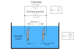
Figure 10 shows the parts that make up an acid, alkali, and salt concentration transmitter.
The working principle of acid, alkali and salt concentration transmitter is as follows: Within a certain range, the concentration of an acid-base solution is proportional to its conductivity. Therefore, as long as the conductivity of the solution is measured, you can calculate the acid-base concentration. When the measured solution flows into the special conductivity cell, if the electrode polarization and distributed capacitance are ignored, it can be equivalent to a pure resistance.
When there’s a constant voltage alternating current, the output current is linear with the conductivity, and the conductivity is proportional to the concentration of acid and alkali in the solution. Therefore, as long as the solution current is measured, the concentration of acid, alkali, and salt can be calculated.
Components
Conductivity cell
Electronic module circuit
Display panel
Case
8. Conductivity Transmitter
A conductivity transmitter is akin to an integrated transmitter. It indirectly measures the concentration of ions by measuring the conductivity of the solution. In addition, it can continuously detect the conductivity of a water solution in an industrial process.
Work Principle
Figure 11 explains the work principle of a conductivity transmitter. Because the electrolyte solution is as good as a metal conductor, electricity current flowing through the electrolyte solution is certain to have the effect of resistance, and it conforms to Ohm’s law.
However, the resistance temperature characteristic of liquid is opposite to that of a metal conductor, which has a negative temperature characteristic. To distinguish it from metal conductor, the conductivity of the electrolyte solution is expressed by conductance (reciprocal of resistance) or conductivity (reciprocal of resistivity).
In a scenario when two mutually insulated electrodes form a conductivity cell, and the solution to be measured is placed in the middle of the cell and a constant voltage alternating current is applied, it will form a current loop.
If the voltage and electrode size are fixed, there’s a certain functional relationship between the loop current and the conductivity. In this way, the conductivity of the solution to be measured can be obtained by measuring the current flowing through the solution.
Components
The components, structure, and circuit of the conductivity transmitter are the same as those of the acid, alkali, and salt concentration transmitter.
9. Smart Transmitter
Work Principle
Figure 12 shows the sensors and microprocessors that make up a smart transmitter. It makes full use of the computing and storage capacity of a microprocessor and can process the data of sensors, including the conditioning of a measurement signal (such as filtering, amplification, analog-to-digital conversion, etc.), data display, automatic correction and automatic compensation, etc.
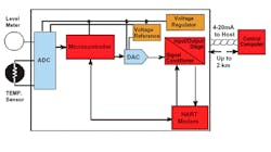
A microprocessor represents the core of smart transmitter. It can not only calculate, store, and process the measured data, but also adjust the sensor through the feedback loop to achieve the best data acquisition.
Because the microprocessor features a variety of software and hardware functionality, it can complete tasks not possible with traditional transmitters. Thus, smart transmitters are able to reduce the manufacturing difficulty of the sensor as well as improve the sensor’s performance in a large range.
Components
Sensing element
Analog-to-digital conversion circuit
Digital-to-analog conversion circuit
Microprocessor
Digital display panel
HART communication element
Advantages of Smart Transmitters
Automatic compensation capability: A smart transmitter can automatically compensate the nonlinearity, temperature drift, and time drift of the sensor through software. It can diagnose errors by itself. After power on, it’s able to carry out self-test on the sensor to check whether each part of the sensor is normal and make a judgment. Its data processing is convenient and accurate. It can process data automatically according to the internal program, such as statistical processing, removing abnormal values and so on.
Two-way communication: A microprocessor can not only receive and process sensor data, but also feed back information to the sensor to adjust and control the measurement process. It can store and memorize information, including characteristic data, configuration information, and compensation records of sensors.
Digital output interface: The output digital signal can easily be connected with a computer or fieldbus.
Summary
Regarding how to select a transmitter, you should consider the actual installation conditions, environmental conditions, instrument performance, economy, and the medium to be measured. In practice, the measuring work can be divided into direct measurements and indirect measurements. Its uses include process measurement, process control, and device interlock.
When you purchase a transmitter, you need to carefully select the appropriate transmitter type and model according to the above purposes.
References
Anna Gries 2011, “What is the functional principle of a resistive pressure transmitter?,” WIKA Alexander Wiegand SE & Co. KG, viewed 12 March 2021.
Control Automation 2019, “What is Hydrostatic Pressure?,” Control Automation, viewed 8 May 2021.
Eastsensor 2018, “Capacitance Differential Pressure Transmitter Working Principle,” eastsensor.com, viewed 13 March 2021.
ForumAutomation 2018, “Basics of smart transmitters, ForumAutomation,” viewed 11 May 2021.
Horiba 2016, “Detector (Reference electrode, Temperature-compensation electrode, Combination electrode),” Horiba, viewed 14 March 2021.
Inst Tools 2018, “Two Electrode Conductivity Probes Principle,” Instrumentationtools, viewed 14 March 2021.
Inst Tools 2016, “Float Type Level Indicator Principle,” Instrumentationtools, viewed 8 May 2021.
Inst Tools 2015, “Float level switch Principle,” Instrumentationtools, viewed 13 March 2021.
InstrumentationToolbox 2011, “Basics of Resistance Temperature Detectors (RTDs),” InstrumentationToolbox, viewed 8 May 2021.
Kirtan Gopal Panda 2016, “Effects of Environment on Accuracy of Ultrasonic Sensor Operates in Millimetre Range,” ResearchGate, viewed 13 March 2021.
Michele Scervini 2009, “Thermoelectric Materials For Thermocouples, Department of Materials Science and Metallurgy of the University of Cambridge,” viewed 12 March 2021.
SMAR International Corp. 2018, “How does the DT300 Density Transmitter work?,” SMAR International Corporation, viewed 8 May 2021.
About the Author
Jane Yu
Product & Content Manager, OKmarts
In the field of industrial parts, Jane Yu is a senior editor with many years of working experience.
Comment About the Article
To join the conversation, and become an exclusive member of Electronic Design, create an account today!

Leaders relevant to this article: