Using USB as a Data Acquistion Interface
Measurement Computing
Learn about the similarities and differences of USB 1.1 and USB 2.0 and how they impact system performance.
USB 1.1 vs. USB 2.0
USB 2.0 is the latest version of the USB specification. To maintain backward compatibility with existing devices, the USB 2.0 operating specification is a superset of the USB 1.1 specification. USB 2.0 does everything that USB 1.1 does and is completely compatible with 1.1. In addition it supports much faster transfers. The maximum data transfer rate in 2.0 is 480 Mb/s, 40 times faster than the highest speed supported in 1.1.
Data Transfer Modes
The USB can be used with a large number of applications. To do so, developers of the USB have created four different data transfer modes: control, interrupt, bulk, and isochronous. Each of these has its advantages and disadvantages, and the application typically will determine which of the modes a USB device uses.
Control Mode
Control transfers are used for configuration and must be supported by all devices. Data acquisition devices requiring very limited data transfer capability may be configured to use only the control mode although most will take advantage of other data transfer modes.
Interrupt Mode
Interrupt transfers typically are used when data must be transferred within a specific amount of time, such as in many data acquisition applications or in a keyboard or mouse interface. Each USB port provides multiple interrupt transfer pipes. The guaranteed timing makes the interrupt mode ideal for use in most data acquisition applications.
A single data acquisition device can use multiple interrupt transfers to provide higher data transfer rates. Since the number of interrupt pipes and overall bus bandwidth is limited, using multiple interrupts reduces the number of independent devices that may be attached to a particular USB port.
Bulk Mode
Bulk transfers typically are used when the transfer rate is not critical, such as writing to a printer. Bulk transfers will use bandwidth that currently is not allocated to other transfer types, so they will not slow down critical operations.
However, if the bus is busy, bulk transfers get the lowest priority. As most data acquisition applications require data transfers to be made on a periodic basis and cannot allow a loss of data, the bulk mode is not recommended for most data acquisition applications.
Isochronous Mode
Isochronous transfers are streaming transfers used for constant rate data, typically audio or video. There is no facility for retransmitting data that has been received with errors, so it is not appropriate for data that must be accurate. This limits the utility of the isochronous mode in most data acquisition applications.
Overall, the interrupt mode provides the best fit for most data acquisition applications. The isochronous mode should be ruled out for most applications due to the lack of data integrity it offers.
The bulk and, to a lesser extent, the control modes could be used to implement many data acquisition devices. But since they do not offer guaranteed data transfer rates, there is a substantial risk of data loss if the data acquisition device does not provide very large data buffers.
As you investigate data acquisition devices from various vendors, ask which transfer mode is used. If the device uses a mode other than interrupt, you should inquire about possible system limitations if you plan to connect more than one device to a given USB port.
Data Transfer Rates
The current USB specification accommodates systems running at three different data transfer rates. Both USB 2.0 and 1.1 support data transfers referred to as low speed and full speed.
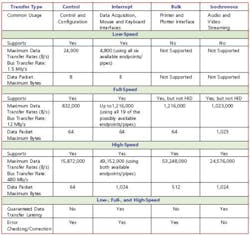
In addition to these rates, 2.0 supports a bus speed referred to as high speed. Table 1 depicts the theoretical maximum transfer rate as well as other specifications related to low-, full- and high-speed transfers.
Table 1. USB 2.0 Theoretical Maximum Transfer Specs
These are theoretical maximum limits that will not necessarily be achieved due to various processing and control overhead requirements.
Based on overhead and processing delay issues, these transfer rates are not achievable in practice. Also remember that most data acquisition applications are based on 12-b or 16-b words rather than bytes, so these numbers must be scaled prior to conversion from bytes per second to samples per second.
Low Speed
Low-speed transfers use a bus transfer rate of 1.5 Mb/s. This is the actual rate at which bits are transferred over the bus and does not include the overhead required for control and error checking. The actual data transfer rates possible in a low-speed system will be considerably less than 1.5 Mb/s.
Low speed also limits the modes of transfers allowed to the interrupt and control modes. Data packets can only be 8 B maximum. The maximum latency for interrupt transfers can be as low as 10 ms. A maximum of 24 B/ms can be transferred with a control endpoint and 8 B/10 ms with an interrupt endpoint.
As a result, devices using low-speed transfers typically are not used for data acquisition applications requiring more than a few kilosamples per second. Many of the currently available USB-based data acquisition products including Measurement Computing's PMD-1208LS and the QUANCOM• USBOPTOREL16 use low-speed transfers.
Full Speed
A full-speed transfer offers a maximum data transfer rate of 12 MB/s. Once again, this is the actual speed that bits are transferred over the bus, and actual usable data transfer rates will be less. All four transfer modes are allowed although only control and interrupt are supported by the stand-ard Windows human interface device (HID) driver.
Data packets can be 64 B maximum for the control, interrupt, and bulk transfers and 1,023 B maximum for isochronous transfers. Maximum latency for interrupt transfers can be as low as 1 ms. A maximum of 832 B/ms can be transferred with a control endpoint, 1,216 B/ms with a bulk endpoint, 64 B/ms with an interrupt endpoint (up to 19 interrupt endpoint pipes are available), and 1,023 B/ms with an isochronous endpoint.
The full-speed transfer mode implements data acquisition devices with sample rates in the 100-kHz range based on interrupt transfers. Measurement Computing's PMD-1608FS and the softDSP SDS 200 use full-speed data transfers. Faster devices could be developed based on bulk or isochronous transfers, but the interrupt transfer method is the most reliable way to ensure accurate data without risking data loss or first in first out (FIFO) overruns.
High Speed
A high-speed transfer offers a maximum data transfer rate of 480 Mb/s and is only supported by USB 2.0 ports. Like the low- and full-speed specifications, this is the actual rate at which bits are transferred over the bus, and with overhead and error checking, the attainable data transfer rates will be less.
High speed supports all four transfer modes. Data packets can be 64 B maximum for control transfers, 512 B maximum for bulk transfers, 1,024 B maximum for interrupt transfers, and 1,024 B maximum for isochronous transfers. Maximum latency for interrupt transfers can be as low as 125 's.
A maximum of 15,872 B/ms can be transferred with a control endpoint, 53,248 B/ms with a bulk endpoint, 24,576 B/ms with an interrupt endpoint, and 24,576 B/ms with an isochronous endpoint. USB-based data acquisition products based on high-speed USB transfers could be expected to support sample rates in the megahertz range.
The USB bus cannot keep up with the 80-MB/s transfer rate possible over the PCI or CompactPCI buses. However, a high-speed USB should accommodate the vast majority of today's data acquisition applications.
The preferred method would be the interrupt mode because it can guarantee timing of the acquisition. Currently, we are not aware of any acquisition device that takes advantage of the capabilities of high-speed data transfers although new products are released quite frequently, and by the time you read this article, there may be.
Mixing Different-Speed Devices on a Single Port
If you are using one USB device or a single USB device per computer port, there are no issues concerning mixing devices of different speeds. If you have a USB 2.0 port, you simply plug in any USB device. The system will recognize the device's speed and communicate accordingly.
If you plug a high-speed 2.0 device into a 1.1 port, the device should be recognized, installed, and actually work. However, you will not necessarily achieve the sample rates that you would obtain from a 2.0 port.
To connect more than one USB device to a single port on your computer, you must install a USB hub. Hubs are available in both 1.1 and 2.0 configurations. You may plug any combination of 1.1 and 2.0 devices into either hub, and they should work.
You also may mix low-speed, full-speed, and high-speed devices on a single hub without typically reducing the performance of the higher speed devices. To take advantage of high-speed transfers, the device, the hub, and the computer port all must be 2.0. The USB has been designed to minimize, if not eliminate, the penalty for mixing older and newer technology.
About the Authors
Nick Wright is a hardware design engineer at Measurement Computing. He has been developing microcontroller-based hardware and firmware for more than nine years, concentrating on communications buses and measurement systems. Mr. Wright also has held engineering positions at Microchip Technologies and Advanced Instruments. e-mail: [email protected]
Bob Judd is vice president of marketing at Measurement Computing. He has been involved in the test and measurement industries for more than 20 years, serving in engineering and marketing capacities at companies including Keithley MetraByte, Datel, and Northrop. e-mail: [email protected]
Measurement Computing, 16 Commerce Blvd., Middleboro, MA 02346, 508-946-5100.
FOR MORE INFORMATION
on Universal Serial Buses
www.rsleads.com/406ee-182


