What Is a Digitizer?

Like other words that have both a basic definition and more specialized technical connotations, the word digitizer means different things to different people. Although fundamentally a digitizer is any device that converts analog signals to a digital form, the term is used by many companies to describe much more than just a bare analog-to-digital converter (ADC).
These products vary in their capabilities, but in general, a digitizer performs many of the same functions as a digital storage oscilloscope (DSO) without the display (Figure 1). The analog input signal may be AC or DC coupled and terminated in 50 W or a high impedance of 1 M W or greater.
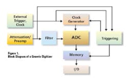
Attenuation or gain often follows, sometimes with anti-alias low-pass filtering. Multiplexed systems have one ADC preceded by a channel multiplexer, but digitizers that simultaneously sample multiple channels use a separate ADC per channel. Digitized signals are stored in onboard memory or transferred to the memory of a host PC.
Functionally, digitizers have one or more inputs, provide a degree of signal conditioning, accept triggers, convert the input signals to digital data, and store the data for later analysis and display. The same things can be said for DSOs, but an engineer’s perceptions of scopes and digitizers are quite distinct.
Scopes have evolved from visual display instruments based entirely on analog circuitry. DSOs can address a much wider range of applications than can analog scopes, but it’s only recently that DSOs have been capable of mimicking the time-dependant intensity gradation of traditional analog scope traces. Even the most modern DSO displays waveforms in the same 8 × 10 division format used for decades by analog scopes.
In contrast, digitizers have their roots in data acquisition technology that initially dealt with multiple channels of low-speed physical parameters such as temperature, pressure, and heartbeats. The sampling rate was controlled by a software-timing loop in the host PC.
So-called software pacing still is offered, but most modern digitizers have an onboard hardware-pacing clock that is specified in time-interval units or as a sampling rate. For example, an ADC convert command signal may be produced every millisecond or at a 1-kHz rate. In a DSO, the time base does exactly the same thing but is specified in units of time per division.
Such a periodic 1-kHz clock could be applied to each of 10 channels in turn, resulting in each channel having a 100-Hz sampling rate. This is termed sequential sampling.
To minimize the difference in time when each of the 10 channels is sampled—the skew among the channels—burst sampling can be used. The sampling clock is set to 100 Hz. But on each clock, the 10 channels are sampled in order at the ADC maximum rate. This could be 10 MHz, for example, resulting in a channel-to-channel skew of only 100 ns instead of 1 ms if sequential sampling were used. Burst sampling commonly is found in multifunction analog-input boards and data acquisition boards with multiplexed ADCs, two related classes of products that also digitize analog input signals.
Some DSOs designed to appeal to digitizer users can change the time-base display to read time per sample instead of time per division. Similarly, some PC software used to view stored digitizer data recreates waveforms in an 8 × 10 division scope-like display.
Typically, a digitizer user is looking for greater accuracy, resolution, memory depth, or flexibility than a scope can provide. The term digitizer implies these things even if they are only partially available in some models. For example, LeCroy’s PXI digitizers offer 1-GHz bandwidth, 2.5-GS/s sampling rates, and memory to 8 Mpoints/channel. Compare these specifications to those of the company’s WaveMaster DSO Series: 6-GHz bandwidth and 10 GS/s on multiple channels or 20 GS/s on channel pairs with up to 50 Mpoints/channel. The PXI format provides system flexibility, but you have to use a scope to sample faster than a few gigahertz.
On the other hand, there are very few ADCs with greater than 8-b resolution used in DSOs at any sampling rate. Nicolet Technologies, now part of LDS Test & Measurement, long known for high-resolution DSOs, has introduced the Sigma 30 with dual 12-b, 10-MS/s channels. The instrument’s 0.25% accuracy reflects the needs of the scientific research market that it serves. Most DSOs claim no better than 1% to 2% accuracy even at DC.
Several modern DSOs do offer so-called enhanced resolution modes based on averaging or filtering techniques; however, absolute accuracy is limited by the input amplifier. The enhanced resolution mode causes bandwidth to drop severely, but it does provide the capability to examine aberrations that otherwise would be invisible to a scope’s usual 8-b resolution.
Because of the great variety of products that all digitize analog signals, the comparison chart that accompanies this article includes diverse entries rather than only high-resolution digitizers.
Current Trends
A Comprehensive Approach
DSOs, digitizers, data acquisition systems, and analog-input boards are being more broadly designed to appeal to all users. Including features from what traditionally have been different types of instruments is intended to support applications that previously could not be addressed. On the other hand, this trend further confuses attempts to clearly differentiate one instrument type from the others.
One example cited by Tom Sarfi, the business development manager at VXI Technology, was the need for built-in attenuation so the digitizer modules would more closely match the functionality of stand-alone instruments. He also listed high sampling rates, long memory, and large common-mode voltages as recent customer requirements.
ZTEC’s Mark Morris, vice president of sales and marketing, commented that the company’s digitizers incorporated onboard data processing to give real-time results. The intention that a module should have the features of a traditional instrument is particularly important to ZTEC. Except for the display, the company’s Model ZT1428 Digitizer, a direct drop-in replacement for the obsolete Agilent Technologies E1428 VXI DSO, is a scope in a VXI form factor.
New Opportunities
According to Gage Applied Technologies’ Sales Manager Dr. Andrew Dawson, many of the company’s latest CompuScope boards are based on high-speed and high-resolution ADCs recently developed for the communications industry. For example, the Model 14100 provides 14-b resolution at a 100-MS/s sampling rate. An indication of the communications-industry influence is the product’s 300-MHz bandwidth.
To View Digitizer Chart1 Click Here
To View Digitizer Chart2 Click Here
To View Digitizer Chart3 Click Here
To View Digitizer Chart4 Click Here
For most digitizing applications, the Nyquist criterion is only a guide to the required sampling rate. Although a signal may be bandlimited, seldom does a sampling rate close to twice the bandwidth capture sufficient detail to accurately determine the degree of distortion or other aberrations. Instead, many companies recommend oversampling by a ratio of 10:1 or more.
In contrast, RF communications applications often use undersampling. The actual signal-modulation bandwidth is many times lower than the sampling rate, but the RF or IF frequency may be much higher. Under-sampling, or subsampling, requires a high bandwidth to accommodate the carrier, but the sampling rate needed to avoid aliasing is determined in relation to the modulation bandwidth, not the carrier frequency.
Gage also has made use of higher density programmable logic devices. Applying high-speed data to very long memories requires the data to be distributed, or multiplexed, among the memory ICs. A dense, field-programmable logic device (FPLD) provides short path lengths for the entire multiplex circuit. Of course, more dense memory devices also allow greater storage depth to be designed into a fixed board size.
Not only are new components available, but diverse applications are requiring their performance. Roy Wan, a product manager at ADLink Technology, highlighted software radio development; radar, sonar, and lidar; nondestructive testing; and military applications as areas that demand high speed, high resolution, and deep memories—far more memory than available in traditional benchtop instruments. Higher resolution brings benefits such as better gray-scale definition in ultrasound images.
Acqiris also targets these applications and has used SiGe for its front-end amplifiers to achieve both low power and >1-GHz bandwidth. To extend commonly available analysis capabilities, Acqiris and RF Engines Limited have partnered in high-speed digitizer development to include large fast Fourier transfer (FFT) algorithms of up to 32 kpoints, running in real time at the full input rate provided by the digitizer.
In addition, Acqiris has developed an interleaving technique used to ensure precise matching among several ADC devices. Based on these technologies and the commercial availability of high-speed ADCs, Klaas Vogel, the general manager of Acqiris USA, predicted that sampling rates up to 8 GS/s at 10-b resolution were practical.
Indeed, higher composite sampling rates have been achieved by multiplexing ADCs in DSOs, but the proprietary ICs are not openly available. For example, in Agilent Technologies’ 54850 Series DSOs, a hybrid 20-GS/s, 8-b converter is used per channel. This device consists of a separate SiGe input buffer driving a large CMOS chip that integrates 80 250-MS/s ADCs together with programmable clock phasing for each one. The performance of this converter is discussed in Agilent’s Application Note 1493.
Strategic Test addresses the multichannel, deep-memory market that doesn’t require stratospheric sampling rates. Many customers have been using CAMAC, VME, and VXI products and would rather have a PC-based system that runs standard data-analysis software. For these applications, the PCI bus speed becomes a limiting factor when data from many channels must be transferred in real time. For example, the data from 50 channels sampled with 16-b resolution at a 1-MS/s rate completely occupies the 100-MB/s PCI bus bandwidth.
For large channel-count applications, the introduction of 500-MB/s PCI-Express technology immediately will provide five times the bandwidth. Bob Giblett, Strategic Test’s president, said that if the proposed higher bus rates up to 16 GB/s are developed, fast, high channel-count systems will get much cheaper because the amount of onboard memory can be greatly reduced. In addition, advances in components such as multiple ADCs on a chip will enable PCBs to challenge the number of channels per board provided by CompactPCI and PXI systems.
Dewetron is using 24-b delta-sigma ADCs to address high-resolution applications. Because 24-b is much greater resolution than actually required to digitize signals of interest, the opportunity exists to ignore most DC signal offsets. In other words, even though the dynamic signal only occupies a fraction of the ADC input range, it still will be converted with at least 12-b to 16-b resolution. The result is simplified input circuitry as well as more straightforward operation.
Although many suitable devices are available off the shelf, obtaining the highest bandwidth or the longest memory capability often requires custom circuitry. National Instruments found this to be the case when the company developed a new synchronization and memory core (SMC) as the common architecture for a range of modular instruments.
To achieve the flexibility, speed, and memory size required, NI used a large FPLD to handle triggering, clocks, signal routing, and general signal management between the host PC and the instrument. In addition, the NI-MITE ASIC deals with the details of full-speed PCI bus data upload/download.
Summary
It would appear that new components and more stringent application requirements are fueling a market push and a pull at the same time. Better performance is needed, and the means to provide it are available. That’s great news for the digitizer user because there is more product choice, and the inevitable competition among vendors should improve value as well.
On the other hand, convergence among DSOs, digitizers, multifunction analog input boards, and data acquisition systems, to the extent that it really is happening, may make product selection more difficult. If you are uncertain that a product suits your application, go back to the basics. What signals do you need to capture? Are their characteristics completely matched by the capabilities of the product?
For example, many telecommunications signals run on balanced differential lines. Does the digitizing product under consideration have a balanced differential input with the correct matching impedance? If not, does any similar product?
If you are working in an industrial environment, is galvanic isolation necessary? Is AC or DC coupling or anti-alias filtering provided, or are inputs to the product presumed to come from a separate signal-conditioning device?
One way to eliminate products early in the decision-making process is to listen carefully to the vendors. For instance, the reply we received from one DSO company was, “DSOs are not digitizers.” In fact, the statement is correct if you’re looking for 14-b resolution across 32 channels on a single board. Maybe it’s a bit shortsighted if a customer actually needs to digitize a 5-GHz signal. There aren’t a lot of choices other than a DSO in this case.
A less biased view will be provided by a company that handles many types of instruments. A salesman for such a company may start with a high-priced solution, but he can suggest both lower cost and different kinds of alternatives. Someone selling only scopes or only analog input boards can’t do that.
When the list of possible application solutions has been sufficiently narrowed, have a technical discussion with a representative from each company. In particular, ask about specifications you don’t find on the data sheets. Accurately acquiring a number of analog signals really is difficult, and companies specify performance in many ways.
One marketing manager commented that customers like specs that are easy to understand. He’s right. A well-organized and clearly stated specification makes product selection much easier. But, what about important, although secondary, performance measures? Some companies, such as Fluke, don’t attempt to address this level of detail in the basic data sheet. However, the company does provide in-depth performance documentation that runs to many tens of pages if you really need to know.
Most companies can give you detailed calibration documentation if asked. Such a test report shows how well the instrument meets all its published specs and often includes additional information such as a scope’s channel-to-channel crosstalk.
Finally, be certain to consider the entire job you need to accomplish. If several products totally address your technical requirements, how do they deal with report generation or archiving, and how easily can the analysis routines be customized if required? Several solutions are supported in today’s instruments, ranging from completely built-in capabilities to open systems that allow you to run Microsoft Word and write your own MathWorks MATLAB routines.
Making the best choice isn’t simple, but at least you have the advantage of starting from the widest range of digitizing products ever available.
August 2004
About the Author
Comment About the Article
To join the conversation, and become an exclusive member of Electronic Design, create an account today!

Leaders relevant to this article: