A good dose of electronic dispersion compensation will open your eyes to 10 Gb/s Ethernet's possibilities.
Because the wiring plant represents a large part of a network's cost, achieving higher data rates over the existing cables obviously is desirable. To facilitate this, the transitions from 10-Mb/s Ethernet to 100 Mb/s and from 100 Mb/s to 1 Gb/s have included migration schemes.
For example, 100BASE-TX, Fast Ethernet, uses two pairs of UTP as does 10BASE-T. Category 5 copper cabling is mandatory rather than optional as it is for 10BASE-T, which also operates on Cat 3 wiring. Two strands of optical fiber can be used as an alternative medium for 100BASE-TX. Although a 100BASE-T2 stand-ard exists that used Cat 3, it was adopted much later than 100BASE-TX and not commercially viable.
Even moving up another decade in speed to 1 Gb/s GbE has been accommodated by autonegotiating adapters that switch among 10 Mb/s, 100 Mb/s, or 1 Gb/s as required. To continue using the installed cable plant, all four Cat 5 pairs typically comprising a cable are required for one channel of 1000BASE-T. There is no migration path for Cat 3 cabling.
Many networks upgraded to fiber-optic cabling when they adopted GbE. In addition to 1000BASE-T on copper, 1000BASE-X GbE is specified for two pairs of STP wiring (1000BASE-CX), but it also operates at 850 nm on MMF (1000BASE-SX) and at 1,300 nm on both MMF and SMF (1000BASE-LX).
10GbE
Today, the discussion is about 10GbE and its optical fiber or copper medium. As defined in IEEE 802.3ak, copper may be the lowest cost solution (10GBASE-CX4), although its reach would be limited to 15 m, and whether Cat 5, 5e, or 6 cables can be used remains unclear. It's specified to run on eight pair twinaxial cable. In contrast, both MMF and SMF 10GbE links defined under IEEE 802.3ae achieve 300-m reach on MMF and up to 40 km on SMF.
The MMF physical layers are 10GBASE-S that uses two fibers at 850 nm and 10GBASE-L4, a WDM specification that also applies to SMF. For SMF, 10GBASE-L defines a 1,310-nm link on two fibers, and 10GBASE-E is a similar link at 1,550 nm.
Further nomenclature describes encoding: X for 8b/10b, R for 64b/66b, and W for WIS that encapsulates Ethernet frames for SONET transmission. Combinations of physical media and encoding designation commonly are used. For example, 10GBASE-ER signifies a system at 1,550 nm using 64b/66b encoding.
For networks spanning up to about 1,000 ft, MMF supports GbE data rates and has the benefit of relatively low cost compared to SMF. On the other hand, SMF is inherently lower loss but, because of its precise termination requirements, more difficult to install. Naturally, it costs more although it provides a more certain upgrade path to 10GbE.
Nevertheless, legacy MMF has been used widely for network backbone connections and to link floors in large buildings. The problem posed by a 10• higher data rate is largely due to greatly increased dispersion in the fiber.
Dispersion
Although there are different causes of dispersion, its effect is to broaden a pulse traveling along a fiber. CD is caused by variation in the index of refraction of fused silica relative to the wavelength of the transmitted light. This means that the various frequency components or colors comprising the pulse travel at different speeds. CD is equivalent to the slope of a fiber's group delay vs. wavelength curve.
PMD results from different propagation rates for horizontally or vertically polarized light. The deviation of the distribution of the refractive index from being exactly circular produces birefringence, the root cause of PMD. Stress or vibration causes geometric changes to the fiber's orientation that interact with its birefringence to affect PMD.1
Multimode cable, by definition, transmits light via a large number of different paths, which produces multimode dispersion. This is the largest cause of dispersion in multimode cable. It is a function of the fiber and the way in which the driving LED or laser has been coupled to the fiber.
The commonly used units of CD are ps/(nm-km). For example, a standard SMF intended for use at 1,310 nm has a typical dispersion of 17 ps/(nm-km) at 1,550 nm. For many reasons outside the scope of this article, operation of SMF at or near 1,550 nm is desirable.
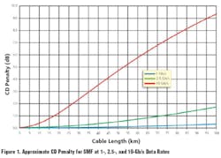
One way of referring to the loss arising from dispersion is to determine the power required to achieve a certain BER for a short length of cable. The additional amount of power required to achieve the same BER through a longer cable is termed the dispersion penalty. Typically, curves are given that relate the data rate to the allowed cable length for a fixed decibel penalty such as 1 dB or 2 dB.
If too much dispersion exists in a fiber, successive pulses may interfere with each other causing ISI, and the link's BER will be degraded. As can be seen from the equation for SMF, the dispersion penalty due to CD varies as the square of the data rate:2
where: Rate = data rate (Hz)
Length = cable length (km)
Width = line width (nm)
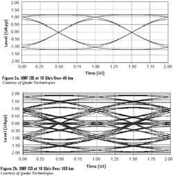
Figure 1 shows the approximate relationship between dispersion penalty and fiber length for data rates of 1, 2.5, and 10 Gb/s. Another way of looking at the interference caused by dispersion is to consider eye diagrams that correspond to the conditions of Figure 1.
For the same 17-ps/(nm-km) cable dispersion and 0.1-nm source line width, Figures 2a and 2b illustrate the drastic signal deterioration that occurs when the cable length is increased from 40 km to 100 km.3 For MMF, eye diagrams for only a 300-m length can appear even worse, being the superposition of many responses having different delays.
Dispersion Compensation
Long-haul networks compensate CD by adding lengths of special cable with negative dispersion characteristics. For SMF, and considering the expense of a long-haul link, this is practical. It doesn t work for MMF because no physical fiber can cancel another fiber's multimode dispersion. Nor does it deal with the variability of PMD that is important at 10 Gb/s in SMF.
The preferred solution is some form of adaptive EDC. Ideally, so-called blind adaptation is required, which needs no a priori knowledge of the fiber's dispersion characteristics the EDC is attempting to compensate.
Three popular approaches are being developed. Two of these can be described as filters, one linear and the other nonlinear.
An FFE is a tapped delay line that produces a weighted sum of the input signal and delayed versions of it. This is a linear filter that can be designed to have a characteristic inverse of the optical channel. In other words, an FFE circuit can undo most of the effects introduced by the channel's dispersion by approximating the inverse of the channel's transfer function.
In a DFE, the decision threshold of the CDR circuit is shifted to compensate for the influence of past data levels. For example, if the previous decided value was a one, the ISI it has caused with respect to the current bit will increase the absolute voltage level. Hence, a good DFE should increase the CDR threshold.
The third equalization technique, the MLSE, treats the channel like a state machine with 2N-1states, where N is the number of symbols contributing to ISI. The Viterbi algorithm is used to select the sequence of N values most likely to have occurred. Although this technically may be the best data-recovery method, the computation overhead at 10 Gb/s makes it impractical at this time.
It generally is agreed that a completely digital compensation system would be advantageous, giving the benefits of low or zero drift over time and temperature, higher accuracy without trimming, and small size/low power if all the circuit functions could be suitably integrated.
On the other hand, given today's technology, a completely digital 10-Gb/s solution is not practical. To implement just the ADC requires interleaving multiple devices, each relatively power hungry. So, instead of a completely digital implementation, some designs use analog FFEs, which reduce the accuracy and resolution requirements of the following ADC.4
In a presentation at the 2004 IEEE MTT-S Conference, the MLSE approach was shown to tolerate at least three times as much total dispersion as a conventional CDR circuit or a DFE at an optical signal-to-noise ratio of 20 dB. In addition, the MLSE function can compensate for pre-cursor effects; that is, the decision threshold is adjusted to account for the ISI effect of future decisions. 5
Testing
Actually, there are two distinct stages to 10GbE adoption, the first not involving EDC and the latter using it. Some networks already are running 10GbE, but only on selected fibers. Typically, the allowable dispersion overhead is kept below 2 dB by choosing cables with the best characteristics and limiting the cable length. In practice, this means that interoperability among equipment from a variety of manufacturers can be a problem.
To ensure interoperability, IEEE 802.3ae defined so-called stressed-eye testing. Rather than limit BER testing only to signal amplitude, stressed-eye testing mimics the kinds of worst-case impairments likely to be seen in real networks. The specification stringently defines a set of impairments suitable for each of several types of links: MMF at 850 nm up to 65-m length, MMF 1,310 nm WDM up to 300 m, SMF at 1,310 nm to 10 km, and SMF at 1,550 nm to 40 km.
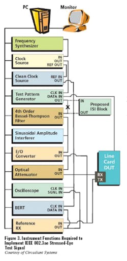
Generating a reliable and accurate stressed eye is not simple. The equipment shown in Figure 3 represents the test setup defined and described in section 52.9.9.1 of 802.3ae:
The fourth-order Bessel-Thomson filter is used to create ISI-induced VECP. The sinusoidal amplitude interferer causes additional eye closure, but in conjunction with the slowed edge rates from the filter, also causes jitter. The nature of the jitter is intended to emulate instantaneous bit shrinkage that can occur with DDJ. This type of jitter cannot be created by simple phase modulation. The sinusoidal phase modulation represents other forms of jitter and also verifies that the receiver under test can track low-frequency jitter.
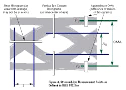
Coincident with the issuing of the standard and the stressed-eye test, some commonly used definitions were revised. In particular, ER, the ratio of the optical power level of a 1 vs. that of a 0, generally has been replaced by the concept of OMA, which is the difference between the two power levels.
If the actual power levels are known, either parameter can be derived. OMA emphasizes that the difference between the two levels, especially in AC-coupled receivers, is important. In contrast, ER implies using a small absolute 0 level to increase the ratio, even though it may be more important to reduce chirp through optimum biasing at a higher 0 level.
Figure 4 depicts the stressed-eye measurement points referred to in the standard. As an example of the corresponding test limits, a 10GBASE-S MMF receiver must achieve a 10-12 BER at the specified operating distance with a minimum of 0.3-UI pk-pk jitter, 3.5-dB VECP, and a maximum 0.18-mW OMA. This kind of comprehensive specification ensures interoperability and is clearly more difficult to meet than a simple sensitivity limit.
Specifying EDC Performance
When EDC is added to a receiver, it is expected to improve performance. In fact, several manufacturers now offer such receivers and typically claim 2- or 3-dB improvement. This means that a longer reach can be accommodated or the link can operate at lower power without sacrificing BER.
EDC is not specifically addressed in 802.3ae. The standard that will address 10GbE operation of MMF links with EDC-enhanced CDR is 802.3aq, currently being developed by the 10GBASE-LRM Working Group and expected to be available by the end of 2005.
At present, the scope of 802.3aq is limited to MMF. According to Paul Fitzgerald, Circadiant System's marketing director, one idea being pursued is to add an ISI generator block to the stressed-eye test setup to modulate the level of the signal ahead of the Bessel-Thomson filter. This is shown with dashed lines in Figure 3. Varying the interferer amplitude among three levels will add additional stress designed to verify operation of EDC schemes.
Conclusion
Achieving a 10• data throughput rate on legacy fiber-optic cables obviously is attractive. EDC is one part of the technology required, and it is receiving a great deal of attention. Also important, for example, are the launch conditions required for enhanced MMF performance.6
However, for the test engineer attempting to verify performance in the field, the introduction of stressed-eye testing poses a problem. At a system level, if all the network elements are 802.3ae compliant, the network should work well. On the other hand, if you want to use a stressed-eye pattern to test a particular link, there is little portable test equipment available.
That's not to say that several companies don't have test solutions. Agilent Technologies, Anritsu, JDS Uniphase, and Circadiant have equipment with which a stressed-eye test signal can be created and its effect measured. Of these, the Circadiant Optical Standards Tester is the most targeted. According to Frost & Sullivan's Jessy Cavazos, Circadiant is the undisputed market-share leader in the stressed receiver conformance testing market, generating more than 90% of the sales of complete instruments so far in 2004.
Most other instruments are larger and less targeted to stressed-eye testing. This means that separate pieces of test equipment must be assembled to build a stressed-eye test system with the associated calibration and interfacing issues. Rather than compete in the laboratory-based parametric test instrument segment, Circadiant, from the company's inception, emphasized a small, single-box form factor and the stressed-eye test capability.
No doubt, as the need for stressed-eye testing expands, other companies will produce instruments with similar capabilities. In the meantime, Circadiant seems to have defined the preferred product for 802.3ae 10GbE testing.
References
1. Girard, A., Ph.D., Polarization of Light in Fiber Causes Signal Dispersion, Technology Note, EXFO, 2001.
2. Fiber Dispersion, http://www.fiber-optics.info/articles/dispersion.htm
3. McPherson, D., Adaptive Equalization for 10 Gb/s Fiber Optic Communication Systems,• IEEE MTT-S Signal Processing Receivers for Optical Fiber Communication Workshop, June 11, 2004.
4. Bhoja, S., 10 Gb/s Adaptive Electronic Dispersion Compensation for Optical Networks,• IEEE MTT-S Signal Processing Receivers for Optical Fiber Communication Workshop, June 11, 2004.
5. Agazzi, O. and Gopinathan, V., A Comparison of Electronic Dispersion Compensation Techniques for Optical Channels,• IEEE MTT-S Signal Processing Receivers for Optical Fiber Communication Workshop, June 11, 2004.
6. 10 Gb/s Optical Transceivers: Fundamentals and Emerging Technologies,• Intel Technical Journal, May 2004, vol. 08, issue 02, ISSN 1535-864X.
FOR MORE INFORMATION
to download IEEE802.3ae free
www.rsleads.com/409ee-214
