Managing Electronics Validation Testing
Even with technology changing faster than validation procedures can be rewritten, it still is possible to perform thorough product testing.
With the ever-changing complexity of automotive electronics and the resulting complexity of hardware/software interactions, validation testing often misses key failure modes and problem areas. Often problems only are found late in a program development or as warranty returns from the field.
Most validation testing is based on a statistical approximation of the expected behavior of a population. For example, if 100,000 units are going to be placed in the field, 12 units may be tested to one equivalent life to demonstrate 90% reliability with 70% confidence. The product is acceptable if all 12 units pass one equivalent life under the test conditions.
Typically, the worst-case conditions are chosen so that 10,000-hour life can be represented by 500 hours at the most severe conditions that take place 5% of the time. Being 90% reliable for the most severe conditions often results in being 99% reliable for the expected normal conditions.
When the research is first done to figure out what the worst-case conditions are and how long one equivalent life is, many assumptions are made. Once the test is established for a given product, it may be used for many years.
As the technology of the product changes, the assumptions in the test may no longer be valid, but they are rarely updated until after there are serious warranty issues. Even then, most companies are unwilling to get rid of a validation test that has been used for many years. Instead, they simply will add a test to address the warranty issues from the new technology.
To make matters worse, additional statistical compromises may be made in the interest of time or resources. For example, 12 parts to one life may demonstrate 90% reliability, but prototypes often are expensive. Using fewer parts tested to multiple lives can yield the same reliability demonstration, but more assumptions about the homogeneity of the failure mechanisms in the product are introduced into the validation plan. Unfortunately, the economic driver to reduce prototype counts is greatest when this assumption is most likely wrong when the device is a complex system involving many different technologies.
These compromises in the validation plan lead to issues being found late in a program when more parts are available for large sample size testing or after the product is in the field. For example, a metal cover is switched to plastic, and the product passes all of the durability and environmental tests that the metal cover had been failing. However, when the product is in the field, there is a rash of failures with the cover cracking near the fastener points.
The root cause could be several things: chemical attack, sensitively to faster torque, cold temperatures, or thermal aging. All of these are stresses the metal part was not susceptible to, so the validation testing did not cover the issues.
Given the challenges of introducing new technology while shortening the development time and increasing expectations for durability and reliability, the validation synthesis must address the following:
• Shorten the overall validation time, not just an individual test.
• Manage the risk of differing result formats and their impact on decision-making.
• Be traceable and defendable to management scrutiny or internal/external audit.
• Be adaptable as the technology and business structures change.
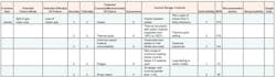
To accomplish this, we will start from the design failure modes and effects analysis (DFMEA) or a similar document (Table 1). Regardless of the document used, there are a few things that it must contain to be effective: an exhaustive list of the potential failure modes that are known, anticipated, or suspected in the product. The failures should be the obvious structural or functional failures of the device plus the less obvious failures of function like a label not being legible.
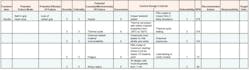
Also, the document must have a list of all of the mechanisms that could precipitate the failure in the product. In a DFMEA, these are the Potential Failure and the Mechanism of Failure columns.
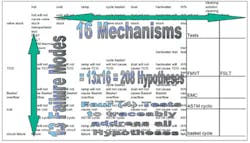
From these columns, a Hypothesis Matrix can be created (Table 21 and Table 3). The Hypothesis Matrix is a cross-reference of all failure modes vs. all mechanisms. For the product to work, it must be true that no mechanism could cause any failure. For that reason, the Hypothesis Matrix contains every hypothesis that must be true for the product to work.
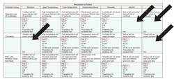
Several things can be done with the Hypothesis Matrix. First, the matrix helps identify if there are any holes in the DFMEA. Because the hypothesis compares all of the mechanisms to all of the failure modes, all mechanisms that could cause a failure must be properly listed in the DFMEA.
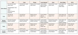
Finally, all of the tests that could be used to check the hypothesis in the matrix can be added to the matrix. From these, the one test that covers the most hypotheses can be identified and the hypothesis that it checks circled. This is continued until all hypotheses are checked at least once. This provides a concise list of tests that traceably satisfies all the hypotheses. Usually this only takes four or five tests (Table 4).
Now compare this to the four criteria. Because the set of tests that comes out of a Hypothesis Matrix includes accelerated tests and any other test that is needed and is invariably a much shorter list of tests, the overall validation plan generally is 50% to 67% shorter.
Because the tests are identified directly with the hypothesis, traceable to the DFMEA, the decision-makers can readily identify the changes they need to make. There are two exceptions:
• If the decisions being made have nothing to do with science, then there will not be a corresponding hypothesis.
• If the decision being made was not properly documented as a potential failure in the DMFEA, then it needs to be added.
Because these tests are traceable to the DMFEA and tied to a complete list of the hypotheses that must be true for the product to work, it actually would be harder to defend continuing with the old test plan than to switch to the new, more efficient, more excusive plan.
Finally, because the test plan automatically updates as the DFMEA changes, then changes in technology and the business structure will cause an update to the validation plan.
This method has been used on appliances with great success and recently in the automotive arena on the Ford GT interior. The DFMEA for the interior identified a set of tests that would exhaustively test the hypotheses that must be true for the interior to work. Using two failure mode verification tests (FMVTs) and three key life tests, five parts were used more than four months to iterate the design more than four times.
The FMVT incorporated all the stress sources that the interior would be subjected to over the course of testing including vibration, solar, humidity, and temperature. Stress levels start at maximum service conditions and ramp up in a step-wise fashion to the destruct limit.
By exposing a product or system to a combined set of amplified environments/stresses, multiple failure modes and their sequence and distribution are produced in a very short time frame. Traditional testing would have taken six to nine months vs. four months and required six to 12 parts. The test plan developed through the Hypothesis Matrix incorporated accelerated testing, traceably satisfied the information needs of the project, and provided four design iterations in as many months.
Reference
1. Porter, A.J., Accelerated Testing and Validation, 2004, p. 195.
About the Author
Alexander J. Porter is the engineering development manager at Intertek ETL SEMKO and has been with the company since 1992. He has three patents related to accelerated testing equipment and authored more than 35 articles and technical papers on accelerated testing and currently serves as an instructor for SAE's course titled Accelerated Test Methods for Ground and Aerospace Vehicle Development.• Mr. Porter holds a B.S. in aircraft engineering and an M.S. in mechanical engineering, both from Western Michigan University. Intertek ETL SEMKO, 3033 Madison Ave. SE, Grand Rapids, MI 49548, 616-656-1348
FOR MORE INFORMATION
on validation testing
www.rsleads.com/609ee-218
About the Author
Comment About the Article
To join the conversation, and become an exclusive member of Electronic Design, create an account today!

Leaders relevant to this article: