TDR Scopes to the Rescue
The transition of the electronics industry to serial data standards and the need for larger amounts of data to be carried by the computer, communications, and consumer device interconnect links have resulted in an industry passage into the gigabit operating regime. At gigabit speeds, high-frequency losses in the system interconnect have much greater impact on the reliable operation of the digital system, decreasing signal rise time and amplitude and degrading the bit error ratio (BER). Additionally, the progression from single-lane to multilane serial signaling generated a need to understand crosstalk in a high level of detail, often measured in the frequency domain.
To understand and address these issues, most digital serial standards now require some form of frequency-domain (S-parameter) measurements for the system interconnects. Differential insertion (Sdd21) and return loss (Sdd11) are typical measurements with differential crosstalk, another form of Sdd21, and some common-mode measurements more frequently included in the compliance testing specification. Practically all serial data standards such as SATA, PCI Express, FB-DIMM, HDMI, and Gigabit Ethernet now require some level of S-parameter compliance testing in addition to the impedance, delay, and skew tests traditionally used for compliance testing of PCBs and cable assemblies.
Measuring S-Parameters
To address this need for frequency-domain S-parameter measurements, serial data designers initially turned to the instrument traditionally used for S-parameter measurements in microwave and RF design: the vector network analyzer (VNA). However, a typical digital designer is not familiar with a VNA and overwhelmed by the complexity of and difficulties with providing appropriate calibration standards for a typical in-fixture, in-backplane measurement.
A much more convenient approach for S-parameter measurements emerged based on TDR sampling oscilloscopes and post-processing software. This methodology has been developed in academia as far back as the 1970s, and its relative simplicity, ease of use, and intuitive nature have come to the rescue.
TDR S-Parameter Calibration
At the heart of most TDR-based S-parameters is the simplified calibration procedure known as abbreviated SOLT. It is possible to use this procedure partially because the source and load match errors can be windowed out in TDR and ignored and also because accuracy requirements are limited to about 40 dB of dynamic range for serial data applications. Using this simplified calibration procedure, the required S-parameter measurements can be performed much more quickly and efficiently.
Additionally, the flexibility of some of the TDR oscilloscope calibration procedures available in the industry makes the in-fixture, in-backplane serial data measurements very easy and straightforward. This simplicity of in-fixture, in-circuit measurements is a critical benefit a TDR oscilloscope can offer to a serial data designer.
The TDR's easy and highly flexible calibration procedure enables other advantages: high throughput, ease of use, and lower manufacturing cost of test. The S-parameter measurement throughput for serial data measurements that can be achieved with TDR oscilloscopes is easily an order of magnitude faster than that of a VNA for typical differential serial data measurements.
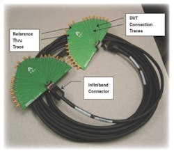
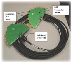
Let's consider the example of an Infiniband test setup (Figure 1). A TDR-based S-parameter measurement system can use the measurement on the reference thru traces as the only calibration measurement and perform a differential insertion-loss measurement with very high throughput. As a result, the cable measurement can be completed in minutes or less.
The same measurement with a VNA would require a full SOLT calibration, a lengthy and error-prone procedure that can take 30 minutes or more to perform. SOLT calibration would be followed by measuring the cable assembly and the fixture, measuring the reference thru traces, and subtracting reference thru measurement from the cable and the fixture measurement.
Frequently, the digital designer obtains less repeatable and less accurate S-parameter measurements with a VNA than with a TDR. The explanation is simple: The VNA is an accurate but highly specialized instrument and not part of a normal toolbox for a digital designer.
Another good example is measuring differential return loss of an active device in a package soldered to the PCB. With the TDR-based S-parameter measurement solution, you only have to supply a reference short waveform by shorting together the two pins or balls of the package within the differential pair of interest.
Removing the shorting connection and powering up the device if necessary will provide the time-domain waveform from which the return loss can be computed. Such a measurement with a TDR-based system will take less than a minute.
When attempting such a measurement with a VNA, a digital designer has to contemplate a special fixture to perform the measurement since it is impossible to directly de-embed the return loss of the PCB from the overall measurement. This measurement can take weeks to accomplish with a VNA, but it can be obtained within a minute or so with a TDR-based system.
Electronic modules have simplified the VNA calibration procedure somewhat, but differential electronic calibration modules are only available to relatively low frequency, and single-ended modules still require a number of connections and reconnections for calibration. Finally, VNA electronic calibration modules do not provide any benefit for in-fixture or in-circuit calibration, leaving the serial data designers stranded since most of their measurements are in-fixture or on the PCBs.
Measurement Accuracy
Accuracy of the TDR-based S-parameter measurements has sometimes been questioned. This is despite the fact that the underlying methodology dates back a couple of decades and was developed by academia and supported by the U.S. National Institute of Standards and Technology.
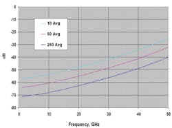
However, accuracy of a typical serial data measurement does not require more than about 40 dB of dynamic range, which is more than adequate on a digital signal (Figure 2). As a result, the TDR-based measurements are highly accurate within the highest frequency range for serial data applications, typically defined as the fifth harmonic of the clock for the given standard. Ample dynamic range is available in TDR-based S-parameter systems, as much as 50 dB to 60 dB at the highest frequency of interest.
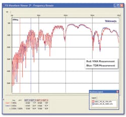
Measurement correlation of the TDR with the VNA also always comes out to be excellent, as Figure 3 illustrates for an SATA device.
Until recently, TDR-based S-parameters techniques have not received large acceptance in the industry because VNAs were the only solution for many years. Today, however, all serial data standards of any importance accept TDR-based S-parameter measurement as the proper solution for S-parameter measurements.
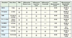
Additionally, sampling scopes, typically the basic mainframe for the TDR measurements, are capable of highly accurate eye diagram, jitter, and noise measurements and BER predictions. A narrowly focused VNA instrument cannot match the versatility of the TDR and sampling scopes (Table 1).
Measurement Tips and Tricks
It is important to follow good measurement practices when working with a 50-GHz TDR oscilloscope. These would include letting the instrument warm up for 20 to 30 minutes before performing measurements, using good quality low-loss cables and good probes with small signal-to-ground spacing, and applying averaging in the TDR oscilloscope to reduce noise.
All waveforms must be acquired without changing the time base on the TDR oscilloscope. The first waveform transition, corresponding to the interface from the sampling head to the cable, must be windowed out. When you look at an open reference waveform, essentially you see a two-step staircase. The first step must be windowed out, and the measurement must be zoomed in on the DUT (Figure 4).
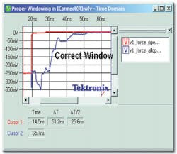
It is important to select a window that is long enough to allow the DUT waveform to completely settle to its steady-state DC level. Since we are about to start making high-frequency analysis of the DUT, we need to allow the signal to settle to make this analysis accurately.
Truncating the waveform before it settles to its steady-state DC level may generate low-frequency errors in the S-parameter computation. In general, for a DUT that is approximately around 50 Ω (100 Ω differentially), the recommended acquisition window length is approximately three to five times the electrical length of the DUT.
Make sure that a sufficient number of data points are selected in the oscilloscope acquisition window. This is particularly critical for analyzing long interconnects such as cables. The upper frequency limit of your measurement is determined as:
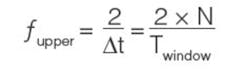
where: N = the number of points in the acquisition window
∆t = the time step
Twindow = the acquisition window length
To get S-parameter data to the desired upper frequency (fupper), make sure that the ratio between the number of points and window length is sufficient. Software with 1,000,000-point acquisition ensures that this will not be a problem for even very long devices.
To increase the dynamic range of the measurements, keep the number of averages and the number of points to the maximum, as indicated in this equation:
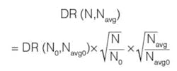
where: N and Navg = the current number of points and averages compared to the previous number of points and averages N0 and Navg0, respectively. Increasing the number of averages two times provides an additional 3 dB of dynamic range. In general, increasing digital averaging in the scope has the same effect as narrowband filtering in a VNA.
When using a forward time-domain transmission (TDT) waveform of the DUT, the resulting S-parameter is insertion loss (S21). If we used a time-domain reflection (TDR) waveform, we would obtain return loss; if we used TDT into the adjacent line, we would obtain crosstalk in the frequency domain.
For differential S-parameter measurements, the oscilloscope must have the two stimulus signals switching in opposite directions. For common-mode stimulus waveforms, the oscilloscope must have the stimuli switching in the same direction.
For differential response, subtract one response channel from the other. For common-mode response, add the two response channels together. In the differential mode, both transmission and reference must be differential; that is, negative switching channel subtracted from the positive switching signal.
The TDR waveform in the S-parameter computation must be acquired with the 50-Ω cables connected to both DUT ports, ensuring a 50-Ω termination at the far end of the DUT. The cables, probes, or fixtures used to connect the DUT to both channels of the TDR oscilloscope are assumed by the TDR analysis software to be of the same length. A differential termination of 100 Ω is acceptable for differential response measurements.
Mode conversion parameters are much less important. But if you need to obtain them, use the same process as for differential-mode or common-mode S-parameters except: ● For differential-mode to common-mode conversion, the stimulus is differential where the acquisition is performed only using the sum of the channels. ● For common-mode to differential-mode conversion, the stimulus is common-mode and the acquisition is performed using only the difference between the channels. Normally, the differential-mode to common-mode differences should be zero across the acquisition window. When there is skew, however, they will be non-zero and produce non-zero frequency-dependent mode conversion. Summary
Together, all these advantages make the TDR oscilloscopes the best solution for the S-parameter measurements in serial data applications. VNAs remain the preferred choice for microwave, RF, and wireless system measurements.
About the Author
Dima Smolyansky has spent his professional career in the instrumentation and measurement industry and currently is responsible for TDR and S-parameter serial data measurement solutions at Tektronix. Over the course of his career, Mr. Smolyansky has published a number of papers and taught short courses on high-speed digital interconnect measurements and modeling. He holds an M.S.E.E. from Oregon State University and an Engineer Diploma (M.S.) from Kiev Polytechnic Institute. Tektronix, 14200 SW Karl Braun Dr., Beaverton, OR 97077, 800-835-9433, e-mail: [email protected]
About the Author
Comment About the Article
To join the conversation, and become an exclusive member of Electronic Design, create an account today!

Leaders relevant to this article: