Common Core ATE for Functional Testing

The approach to high-end aerospace/defense test system development is shifting from application-specific systems to common core automated systems to reduce overall cost and increase flexibility. Common core test sets also are replacing proprietary legacy systems by using commercial-off-the-shelf (COTS) hardware and open software environments. What's more, common core test sets allow the customer a seamless transition from product design to product validation to production.
One example of a common core automated test system was developed recently by G Systems under a subcontract for Lockheed Martin Missiles and Fire Control (LMMFC) in Dallas to test and validate multiple functions of a new missile launcher for the Non-Line-of-Sight-Launch System (NLOS-LS) (Figure 1). The NLOS-LS is being developed for the U.S. Army's Future Combat Systems (FCS).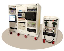
The FCS NLOS-LS spin out one consists of a Precision Attack Missile (PAM) and a highly deployable, platform-independent C/LU with self-contained tactical fire control electronics and software for remote and unmanned operations. Each C/LU will consist of a computer and communications system and 15 missiles.
The test platform is primarily PXI-based and provides a wide array of instrumentation for complete coverage of test program sets in a single system. The PXI hardware, including a counter/timer, DMM, multiplexers and switches, and I/O boards is from National Instruments (NI) and other members of the PXI Consortium.
The RF signal generator, signal analyzer, and modular power supply are from Agilent Technologies. The test set also incorporates multiple interconnect systems using a Virginia Panel receiver and interchangeable test adapters (ITAs) as well as a full complement of custom cable harnesses.
The test system includes self-contained wrap-around capability for performing automated self-test on the instrumentation and interconnects. A wrap-around test is a cost-effective method for testing hardware, cabling, and connections. A signal is generated by one instrument then wrapped around the test set, through the ITA, and measured by another instrument.
The system performs standard DC measurements, RF spectrum analysis, waveform analysis, Ethernet validation, USB validation, and JTAG testing. Other instrumentation includes global positioning system (GPS) simulation, electronic loads, power supplies, dense switching, and general-purpose data acquisition.
The common core platform is controlled using custom software based on NI's TestStand, LabWindows/CVI, and interchangeable virtual instrument (IVI) drivers. All results are archived in an SQL Server database.
The system provides a flexible platform for multiple test programs and a built-in self-test routine for the complete system. Overall, this new test platform reduces both test cost and test time.
Hardware
The missile-launcher test system is based on a hybrid design including PXI-based test hardware as well as box instruments. All of the integrated hardware is COTS to reduce cost and increase system flexibility.
The primary capability of the test set is functional testing of the NLOS missile launch station and related equipment and subassemblies. An additional power supply and electronic load used in testing the launcher under maximum power conditions are housed in the auxiliary power rack.
An industrial PC serves as the test executive controller for the entire suite of test-set hardware. The PXI hardware consists of two PXI instrument chassis and instrument modules including a counter/timer for signal synchronization, a DMM for signal measurement, several multiplexers and switches for signal switching, and multiple I/O boards for data acquisition.
Also integrated into the test set are an RF signal generator, a spectrum analyzer, a GPS simulator, and a DSO. Multiple power supplies and electronic loads provide power to the UUTs and simulate real-time field-test conditions. All instrumentation is connected through a double-height Virginia Panel Series 90• Receiver.
With the test-executive PC, seamless communications with the peripheral instrumentation via the PCI bus, USB, Ethernet, or IEEE 488 are possible. As a result, the test system can use the best instruments for the required measurements without being constrained to one communications bus.
To test multiple launcher systems while using the same common core test set, various ITAs were built to connect to the mass interconnect receiver. The Virginia Panel adapter provides the electrical and mechanical connection to multiple UUTs via unique ITAs to maximize the test set functionality and usage.
Software
The modular test-system software architecture consists of a system management layer or test executive, application-specific software, and an instrument driver layer (Figure 2). This approach supports testing multiple products and facilitates adding tests or hardware. It also enables the use of the same test software for design, validation, and production and reduces delays during the transition from design to manufacturing test.
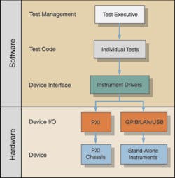
Figure 2. Modular Test System Architecture
A test executive is a sequencing framework for running specific test steps. G Systems uses NI TestStand for its test executive software, which allows many of the common requirements to be standardized in the common core test set. Such functions as the operator interface, UUT tracking, test-flow control, and results filing and reporting are the same for all UUTs, so a common test-executive program saves time when multiple system-level tests are required. The common core test set enables engineers to standardize their system utilities such as self-test and test reporting yet customize specific UUT tests.
IVI Drivers
Another feature of the common core test set is the extensive use of IVI drivers. Test systems designed with IVI drivers allow the same software code to be used with different instrument platforms.
In other words, where IVI drivers are used in the test software, instruments can be exchanged, even those from different manufacturers, with no expensive software updates required. This feature is particularly beneficial when an engineer wants to update a test instrument or if an instrument must be replaced due to obsolescence. With test sets supporting defense systems that are deployed and supported for 10 years or longer, hardware replacement or upgrades are the norm.
In addition, IVI drivers permit instrument simulation prior to full system integration, which allows developers to test their software prior to buying expensive measurement hardware.
Self-Test
A self-test of the test system ensures that all hardware and instrumentation are functional and within specification. Self-testing the hardware is accomplished through a custom ITA interface and software developed in LabWindows/CVI and linked to the TestStand test executive. The self-test ITA has functional stimulus, response, and switching wrap-around for test-station hardware verification and confidence checking.
Each instrument manufacturer's internal built-in self-test (BIST) verifies the function and operation of the instrument being tested. G Systems• self-test software calls the available instrument's internal BIST to verify communications with the instrument. It tests the necessary functions to verify the input and output as well as the cabling between the ITA and the instrument.
Available IVI drivers, along with built-in TestStand IVI step type, take advantage of the unique IVI architecture. It provides an abstraction layer so that any IVI-compatible instrument can replace the existing instrument in a given class.
The system self-test uses existing hardware and does not require any additional instrumentation, which minimizes cost, wiring complexity, and overall system weight. Performing a self-test on one instrument also tests any complementary instrument channels/functionalities to minimize self-test time. An example of this technique is to use the test station's oscilloscope to read the signal generator's signal and test two different instrument functions with one test.
All inputs and outputs from each instrument are connected through the Virginia Panel adapter that provides complete wrap-around verification. Wrapping of I/O modules is accomplished within a given card or between two similar cards, which minimizes the wiring in the self-test ITA.
In general, a test passes if the captured signal is equal to the generated signal within a specified tolerance limit. Some of the tolerance limits are programmatically generated or retrieved while others are configured through sequence file global variables in TestStand.
The self-test sequence was developed in TestStand Sequence Editor with code modules developed in LabWindows/CVI. Test results are displayed on the operator's GUI and contain the test number, test step name, test compare type, measured value, lower limit, upper limit, units, pass/fail status, and information regarding possible cause of failure.
Custom GUIs
The common core test set features several levels of custom-designed GUIs. Engineering views allow complete diagnostics and provide all parametric test data results. In the operator view, the GUIs supply basic self-test instruction and generic pass/fail status.
Mass Interconnect
For a test system to be truly common core and support wide measurement requirements for multiple systems, it must have the capability to interconnect to all the integrated hardware and I/O and all UUTs. Mass interconnect can be defined as an electromechanical device used in conjunction with ATE that reliably connects a multitude of signals simultaneously.
A key feature of the G Systems solution is the mass interconnect panel. The interconnect for the test station uses the Virginia Panel Series 90 Test Panel Receiver with a double-tier frame that aligns with the dual PXI chassis (Figure 3). Large cable bundles are strain relieved at both the receiver and PXI board connections. The receiver panel also hinges down in front of the PXI chassis for easy access and maintenance.
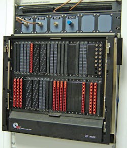
Figure 3. Mass Interconnect Receiver
With this receiver configuration, there is room for all the box instrument connections as well. The existing system has more than 2,500 connection points but still provides space for expansion should new instrumentation or additional PXI cards be required. With proper interconnect planning, an ATE configuration can support decades of future production and test engineering by allowing for hardware replacement and reconfiguration.
Data Storage and ReportingThe magnitude of tests performed with the common core test set requires a database for data storage, data retrieval, and data reporting. By using TestStand Database Options, it is very easy to customize one of the default database schemas and enable database results logging with the click of a button.
To keep the test report size to a minimum, the ASCII format was selected in the TestStand Report Options. The ASCII report consists of approximately 4,000 test results, and these results also are logged to an SQL Server database.
Why Outsourcing?
Through outsourcing, the defense contractor effectively increases its internal resources. Outsourcing allows the defense contractor's technical staff to focus on major systems-level issues. Moreover, outsourcing can be instrumental in meeting critical deadlines.
G Systems completed the common core test station in four and one-half months while the customer had projected six to eight months for an internal design and build. The timesavings kept the program on schedule.
G Systems• expertise spans from test-system design to implementation including hardware, software, SPC analysis, and results reporting. Assembling all of these skill sets in-house can be challenging. By outsourcing, the customer pays for exactly the service they need when they need it.
ConclusionG Systems• new automated missile-launcher test station reduces both system test time and overall system test cost for Lockheed Martin Missiles and Fire Control. The test station uses a modular hybrid design architecture that provides maximum flexibility for hardware expansion or hardware replacement.
The test software uses IVI drivers that facilitate hardware exchange without expensive software upgrades. All the hardware and software are COTS products that replace more expensive proprietary legacy systems.
G Systems cut test system development time from design to implementation nearly in half. The new system also reduces any production start-up delays by using the same system hardware and software for product design through production.
About the Author
Andrew Kahn has been the marketing manager at G Systems since 2005. His previous experience included positions as adjunct professor at the University of Dallas Graduate School of Management, director of marketing at Optek Technology, and manager of business planning at DFW International Airport. Mr. Kahn received a B.A. in chemistry from Wake Forest University and an M.B.A. from Carnegie-Mellon University. G Systems, 860 Avenue F, Suite 100, Plano, TX 75074, 972-516-2278, e-mail: [email protected]
About the Author
Comment About the Article
To join the conversation, and become an exclusive member of Electronic Design, create an account today!

Leaders relevant to this article: