All the Cool VNAs Are Nonlinear
Nonlinear Models
Nonlinear VNA (NVNA) development has continued for more than 20 years, and many of the early researchers have remained involved. The result of various alliances and technical approaches is a group of similar but distinct modeling methods.
Mixer-Based VNA Parameter Extraction
When a mixer-based VNA is used to determine S-functions or X-parameters, each harmonic is applied one at a time with a known phase relative to the large-signal fundamental. This requires the addition of a phase-stable comb generator reference source because this type of VNA loses phase synchronism between acquisitions.
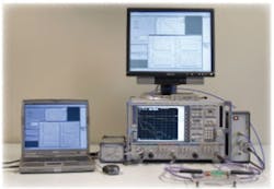
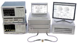
The NMDG ZvxPlus Nonlinear Extension Kit for Rohde & Schwarz ZVx VNAs consists of a harmonic phase reference that achieves the necessary phase calibration, a synchronizer used in the reconstruction of time-domain waveforms, a connection kit, and supporting software. The combination of phase reference and VNA determines the magnitude and phase of all harmonics, and the associated software calculates the S-function ratios. Figure 1 shows the ZvxPlus Kit connected to a Rohde & Schwarz VNA with a DUT in place.
Agilent’s N524xA Series of PNA-X VNAs also is mixer-based and covers the frequency range from 10 MHz to 50 GHz in four models. Nonlinear device characterization is accomplished by adding one or more of options 510 Nonlinear Component Characterization, 514 Nonlinear X-Parameters, 518 Nonlinear Pulse Envelope Domain, and 520 Arbitrary Load-Impedance X-Parameters as well as relevant load-pull tuners and calibration standards.
The company’s NVNA brochure explains that the Model U9391C Comb Generator (10 MHz to 26.5 GHz) or the Model U9391F (10 MHz to 50 GHz) is used “as the NVNA’s harmonic phase reference and provides exceptional performance, frequency range, and ease of use.”
According to Loren Betts, application engineer/scientist at Agilent, “X-parameters include the magnitude and phase of the fundamental signal, its harmonics, and intermodulation products. X-parameters can also define the device’s dependence on load impedance when the NVNA is used in conjunction with load-pull tuners from Agilent channel partners such as Maury Microwave.”
Gary Simpson, chief technology officer at Maury, elaborated. “Our business is offering systems to create X-parameter files vs. source or load fundamental impedance, source or load harmonic impedance, power, bias, frequency, and other stimulus variables that may be available in a particular lab setup…. To validate simulation using X-parameters, we compared it to the load-pull data that is independent of the simulation,” he continued, “and found that the X-parameter simulation matches measured contours and time-domain waveforms with extremely good accuracy.”
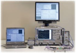
Maury has introduced a new version of load-pull software highly optimized for operation with X-parameters. It fully supports fundamental load- and source-pull and also harmonic source- and load-pull with or without X-parameters. Figure 2 shows two Maury tuners and an Agilent VNA configured for nonlinear measurements.
A great deal of flexibility is provided by the combination of X-parameters and Agilent’s Advanced Design System (ADS) Circuit Simulator. A recent paper by Verspecht, Betts, Root, and others described ADS-enabled time-domain extensions to X-parameters resulting from collaboration among researchers at Jan Verspecht b.v.b.a., Agilent, and the University of Leeds.
An underlying assumption when working with X-parameters is the quasistatic nature of the system; that is, its time invariance. This restriction limits the usefulness of X-parameters in relation to devices that exhibit long-term memory effects. The researchers, “…identified [memory effects] from pulsed envelope transient X-parameter measurements on an NVNA. [This work]…extends the X-parameter paradigm and PHD model to long-term dynamic memory effects such as self-heating, dynamic bias effects, and trapping phenomena…. The model is implemented in the ADS circuit envelope simulator.”5
Sampler-Based VNA Parameter Extraction
In contrast to a mixer-based instrument, a VNA based on harmonic sampling technology simultaneously captures the DUT output at the fundamental and all harmonic frequencies. The phases and magnitudes of the individual harmonics can be determined and the PHD ratios derived for this type of VNA as well.
Because the relative phases of the harmonics are known together with their amplitudes, a large-signal VNA can present results in four ways: as incident and reflected waves or as voltages and currents, both representations in the frequency or time domains.
According to an Anritsu product brochure, “The VectorStar™ VNA optimizes broadband dynamic range performance by utilizing harmonic sampler architecture and including nonlinear transmission line (NLTL) technology, also known as shock-line transmission…. [It includes] a menu-driven capability to control up to four external sources in addition to the internal source and receiver. Control of external sources is completely synchronized to provide the ability to test devices under conditions where phase coherency is a must.”6
The SM6435 Nonlinear Accessories together with a VectorStar MS4642A VNA make up an SM6430 Nonlinear Measurement System. The nonlinear accessories include the elements required to perform real-time load-pull measurements and analyses and comprise MMSNT_LP software to perform fully automated harmonic load-pull analysis, the RTTSWB Test Set that routes and switches the nonlinear signals, and RTT0812 Ultra Low Loss Couplers with less than 0.05-dB insertion loss at 2 GHz. The optional RTTLUS Active Loop Tuner is used to implement active harmonic load-pull.
Steve Reyes, product marketing manager at Anritsu, emphasized the importance of obtaining device performance data under real operating conditions: “A critical element of nonlinear analysis is load-pull measurements, especially harmonic load-pull. This is because of the high harmonic content of the nonlinear devices. To achieve the highest performance, the match presented at both the device input and output must be optimized for the fundamental and harmonic frequencies.
“By inserting an ultra-low-loss coupler between the DUT and tuner, our VectorStar Nonlinear System achieves high measurement accuracy, can monitor the impedance in real time, and allows immediate display of responses,” he continued. “Because the tuner is located after the coupler rather in the traditional position ahead of it, the tuner no longer needs to be precalibrated nor does it even need to be repeatable. Active tuners are preferred because many classes of nonlinear amplifier operation ideally require a reflection coefficient of 1.0 at harmonic frequencies. We support both passive and active tuners and even a mix of types from different manufacturers.”
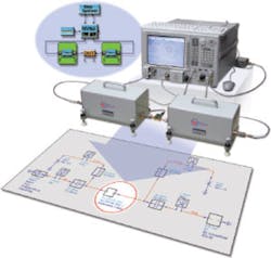
The VectorStar Nonlinear System is the result of collaboration between Anritsu and HFE. The HFE software provides the nonlinear information in a number of formats and complements the HFE test set that also is part of the system. A typical test setup is shown in Figure 3.
A paper by Verspecht, De Groote, and Teyssier describes a similar test setup featuring low-loss couplers that the authors call wave probes. In addition to the advantages cited by Anritsu’s Mr. Reyes, placing the couplers directly between the DUT and input/output tuners “allows determination of the amplitudes and phases of the fundamental as well as all significant harmonics of the RF signal. As such, the data can easily be transformed into the time domain.”7
The paper also contains a detailed discussion of the wave probe operating principles. Basically, the probe has equal electric coupling and magnetic coupling, which constructively interfere in one arm and destructively interfere in the other. This gives the probe its directivity. This type of probe had been reported as early as 1946.
Direct Nonlinear Waveform Engineering
Passive tuners change the impedance of the DUT source or load. Often, a tuner is driven to simulate a large array of complex impedances as other parameters such as power output or efficiency are measured. Software then can sort out optimum operating points from the acquired data.
Alphabetical amplifier classifications have reached well beyond the basic A, B, AB, and C to include many discontinuous switching modes of operation. Especially for these kinds of circuits, performance depends on the impedance at multiple harmonics, not just at the fundamental frequency.
It’s possible to implement cascades of passive tuners or to use special tuners that handle one or more harmonics. However, with these setups, the achievable reflection coefficient or gamma is reduced by system losses. In contrast, an active tuner applies gain to achieve the required impedance as well as gamma close or equal to 1.0 at the DUT.
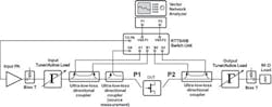
Closed-loop active tuners traditionally have been difficult to implement. Nevertheless, there are successful examples such as the RTTLUS Active Loop Tuner available from Anritsu/HFE. Alternatively, Mesuro has developed an unconditionally stable open-loop Arb-based system that directly generates the required source and load impedances at fundamental and harmonic frequencies (Figure 4).
This is an equivalent but very different way to achieve DUT operation under varying impedance conditions. The Tektronix Arbs that Mesuro uses, “…enable the injection of any special components into the DUT input and output and manipulation of the current and voltage waveforms that exist at the device. In other words,” explained Johannes Benedikt, chief technologist at Mesuro, “it enables a complete source- and load-pull solution not only at the fundamental and harmonic frequencies, but also at baseband spectral components.
“This source- and load-pull system, completely based on electronic instruments, adds speed and flexibility to the acquisition of load-pull data when compared to mechanical alternatives,” he continued. “The Tektronix AWG7000 Series Arbs can create and fully control wideband phase-coherent multichannel signals for the baseband, fundamental frequency, and several harmonics. All signals are sample aligned and phase coherent so there is no need for synchronizing multiple signal generators, extensive phase calibration, or multiple harmonic tuners.”
Because a sampling scope is used to simultaneously acquire all DUT waveforms, the data inherently has coherent spectral component alignment. This means that genuine voltage and current waveforms that represent the actual physical properties of the device are obtained. These waveforms can be compared to theoretical waveform templates for a specific amplifier class. Iteratively adjusting the equivalent source and load impedances to minimize the difference between actual and theoretical waveforms optimizes performance. Matching networks then can be synthesized using the optimum harmonic terminations as a target.
Rather than create a large grid of complex load impedances to cover an area of the Smith chart, Mesuro makes directed changes that cause performance to approach the ideal. Much less data is generated and in a shorter time. Acquired data can be saved into an MDIF file and used with a circuit simulator. Alternatively, the set of measurements can be converted into a PHD model variant that has been developed by Cardiff University and is directly compatible with AWR’s Microwave Office® simulation suite.
Conclusion
There’s no shortage of test instruments that address large-signal nonlinear RF and microwave design. Many approaches build on your previous work with traditional electromechanical tuners. Nevertheless, there are differences among the techniques, Mesuro’s waveform engineering method perhaps being the most distinct.
If you already have a VNA, chances are that a complete nonlinear upgrade kit is available so you can convert it for nonlinear use. And, it’s a short step from nonlinear measurements to a model that can be used with your favorite simulation software. The most important thing is to realize that you cannot use small-signal S-parameters to characterize nonlinear large-signal DUT behavior.
References
- OpenWave Forum, www.openwaveforum.org
- Lecklider, T., “Boldly Going Beyond S-Parameters,” EE-Evaluation Engineering, April 2009, pp. 18-25.
- Franz, M. O., and Schölkopf, B., “A Unifying View of Wiener and Volterra Theory and Polynomial Kernel regression,” IST-2002-506778.
- Verspecht, J., and Root, D., “Polyharmonic Distortion Modeling,” IEEE microwave magazine, June 2006, pp. 44-57.
- Verspecht, J., et al, “Extension of X-Parameters to Include Long-Term Dynamic Memory Effects,” IEEE IMS Proceedings, 2009.
- “MS4640A Series 70 kHz to 70/110/500 GHz and Beyond: Family of RF to Microwave and Millimeter-wave Vector Network Analyzers,” Anritsu.
- Verspecht, J., et al, “Advanced Time Domain Loadpull Technique for Characterization of Microwave Power Transistors,” ESA Microwave Technology and Techniques Workshop, 2008.
| FOR MORE INFORMATION | Click below | |
| Agilent Technologies | N524xA PNA-X NVNA | Click here |
| Anritsu | SM6430 VectorStar Nonlinear Measurement System | Click here |
| AWR | Microwave Office Software | Click here |
| High Frequency Engineering Sagl | RTT Real-Time Tuning System | Click here |
| Maury Microwave | MT993D03 Enhanced Time-Domain and X-Parameters Load Pull Application | Click here |
| Mesuro | MB20/MB150 Nonlinear Test Set | Click here |
| NMDG | ZvxPlus Nonlinear Extension Kit | Click here |
| Rohde & Schwarz | ZVx VNA | Click here |
| Tektronix | AWG7000 Series Arb | Click here |
April 2010
About the Author
Comment About the Article
To join the conversation, and become an exclusive member of Electronic Design, create an account today!

Leaders relevant to this article: