Protocol-Aware ATE Digital Instruments
You could argue that we have entered the post-PC era. However, one thing is certain: We are definitely in a wireless mobile era. What started 10 years ago with 1,000 songs in your pocket has become the entire world in your pocket.
Enabling this transformation have been the steady and unrelenting gains in semiconductor-device design software, process technology, and packaging. The improvements in these processes and tools have allowed designers to leverage existing IP silicon cores to bring highly complex system-on-a-chip (SoC) designs to market faster than ever. These designs typically contain multiple independent cores that communicate both internally and externally using standard and/or custom asynchronous protocols.
While the advances in the design and process areas of the semiconductor value chain have been impressive, the basic system architectures and processes for developing test programs for this latest generation of SoC devices have, until now, remained fundamentally unchanged.
ATE Digital Pattern Generators
The venerable stored-response test system architecture for digital instrumentation has served the industry well since the shift register-based pattern generators of the 1970s. Algorithmic digital pattern generators were added to facilitate testing as memory size became impossible to test with flat patterns.
In the 1980s, ATE pattern generators were enhanced with digital source and capture engines along with the capability to control and synchronize analog instrumentation to support mixed-signal device test. By the late 1980s, structural test in the form of scan was introduced as a way to improve quality, manage complexity, and reduce test cost. This evolution led to the need for the pattern generator to support scan-test requirements.
In the last 10 years, designers of ATE pattern generators started to move beyond just the synchronized triggering of analog instruments from the digital pattern to the complete programming of an instrument’s parameters from the digital pattern. Pattern-Oriented Programming (POP) was created to move the control of an instrument from the relatively slow system computer and data bus to the high-speed digital pattern, minimize instrument setup overhead, and reduce test times to approach device-limited test time. All of these evolutionary changes have helped keep test costs down.
However, the fundamental architecture of the digital pattern generator and its inherent limitations have not changed. Today’s pattern generator basically is a large randomly addressable memory that works best when the tester controlling the device’s timing knows what data should be sent to the device and received from the device. Performing real-time interaction with the device or conditional branching is limited, and therefore, nondeterministic device behavior can only be evaluated outside of the digital pattern flow. The architecture of the traditional ATE digital instrument has been based on the tester providing the control of the device, providing a known pattern to the device, and receiving an expected pattern from the device.
Protocol-Aware Digital Pattern Generators
Today’s device designs are pushing the limits of traditional pattern generator architectures. Modern SoC designs integrate multiple high-level functional blocks. These blocks operate independently from one another, having their own timing generation and distribution.
The programming of these device blocks usually is done through standard interfaces using JTAG, I2C, MDIO, PCIe, or other proprietary communications protocols. Many of these protocols require real-time handshaking between the tester and the device for acknowledging a transaction or qualifying nondeterministic data.
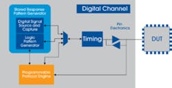
Hardware based Protocol-Aware (PA) ATE represents a revolutionary advance in pattern generator architecture. By adding dedicated programmable PA engines to the pattern generator, it is possible to natively test protocol-based I/O (Figure 1). The tester now is capable of performing real-time communications with the device in the language of the protocol.
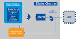
The PA engines have their own timing and memory and can operate independently from the primary pattern generation function (Figure 2). Timing is independent, and engines can act as either master or slave to the DUT. This approach accommodates timing uncertainty when the device blocks are operating asynchronously relative to each other.
Traditionally, when converting asynchronous I/O pattern data from simulation to digital test vectors, assumptions must be made regarding the pattern data’s relative position in time. In the real world, these relationships will vary with process, temperature, and voltage. Data expected in one cycle may move across tester cycle boundaries. PA engines can track these changes and stay locked to the DUT.
There are communications protocols that require the test system to handshake with the DUT. In some cases, the handshaking can be supported with traditional pattern generators containing functions such as conditional branching or match mode. This approach becomes very difficult or impossible to implement if multiple devices are tested in parallel and/or if concurrent test techniques are to be implemented.
The challenge comes down to being able to match and hold synchronization for each individual device block and from device to device in a parallel test scenario. The task becomes unwieldy at best and in some cases impossible. In addition, long pipeline flushing delays in the test instrument caused by conditional branching can result in missed DUT response data or a missed acknowledgement in a handshaking sequence. Dedicated PA engines can be optimized to overcome the problems of a traditional pattern generator by minimizing latency and allowing a real-time response to DUT requests.
PA engines also have the capability to cope with nondeterministic data from DUT outputs. In a hardware-based PA ATE, the PA engine can wait in real time for a qualifying data sequence or device flag to indicate valid data is available. Each PA engine is independent and can easily support multisite and concurrent test. In software-based PA ATE, nondeterministic data must be captured, moved, and analyzed outside of the operation of the pattern generator. This can add significant test time and program complexity.
DDR Device Interfaces
With traditional pattern generators, it is not possible to hand over control to the DUT. Devices containing DDR controllers expect to interact with the ATE as if it were a DRAM. In PA-based systems, the PA engine can be configured to respond to the DUT as if it were a DRAM. Without PA capability, the test engineer must resort to the addition of “golden” memories on the device interface board (DIB).
Unfortunately, the on-DIB memories’ response characteristics cannot be controlled to verify the DUT’s response to the natural variability found in real-world conditions. This results in lower yields due to increased guarding or, worse, inferior quality levels.
System-Level Test
There are cases where the traditional pattern generator imposes unacceptable test compromises in the standard test flow of wafer probe and final production test. Test engineers may have to resort to an additional system-level test (SLT) insertion to be included in the overall test flow. SLT is a modified form of the device’s final application that enables the device’s interfaces like PCIe to operate in a complete “mission mode.” This adds cost and time to the overall manufacturing process. Hardware-based PA ATE can test complex, high-performance interfaces like PCIe at speed, in mission mode, in a single insertion.
Reconfigurable and Programmable PA Engines
Since protocols are evolving, it’s not enough for PA-based ATE to be hardware based, and even standard protocols can be subject to interpretation and inconsistency of implementation. Additionally, semiconductor manufacturers may use proprietary protocols. To address this, the PA engine architecture should support instruction sets and APIs that allow users to create and modify protocols.
An example of such a programmable PA instrument is Teradyne’s UltraPin1600. The PA engines are reconfigurable depending on the desired protocol family. For DDR controller testing, the PA engine is programmed to respond to the DUT like a DRAM, eliminating the need to design DRAMs onto the load board. For some of the less complex protocols like JTAG, SPI, MDIO, or SLIMbus, the PA engine is configured as a user-programmable state machine with an instruction set optimized for the creation of protocols.
For example, there is a series of instructions that support handshaking and nondeterministic behavior during a transaction. Using Protocol Studio, Teradyne’s protocol editing and creation software, the test engineer can modify the standard library of basic protocols or create a custom protocol.
For complex, well-defined standards, the implementation should be easily reconfigurable using standard-certified IP to guarantee adherence to the protocol and accurate verification of the chip design. Teradyne uses this approach for the implementation of PCIe PA. The UltraSerial10G incorporates a standard-certified PCIe core as part of the PCIe PA solution, ensuring compliance to the PCIe standard.
PA Software
Hardware enhancements to the digital pattern generator can improve cost-of-test and quality. Time-to-market also can benefit from PA. Chip designers have had access to high-level hardware and software tools to develop and debug the device interface designs. Protocol analyzers and traffic generators bring efficient intuitive tools to the process. Designers can program tests in high-level, easily understood syntax to program the device functions.
With the traditional ATE pattern-generator approach, these high-level register-based tests are run through the device simulation and converted into the 1s and 0s of a digital pattern. This complicates readability of the data by the test engineer when debugging. The test engineer struggles to interpret the ATE results and map them back into the original high-level input. PA software maintains the high-level context found at the device verification level, the same level used by the designer.
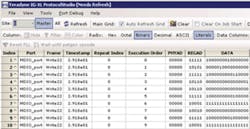
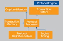
Figure 3 is a screenshot from Teradyne’s Protocol Studio. In Teradyne’s PA Architecture for nWire, protocols are built using the protocol editor, and Protocol Studio is used to interactively debug and analyze transactions. In this example, Protocol Studio is displaying a series of MDIO transactions. All of the necessary information to interpret the intent is clearly shown. In this case, a clause 22 write operation (Write22) is indicated by the frame type.
The payload consisting of the physical address, register address, and data also is presented in a clearly readable fashion. Updates to the payload are interactive, making device debug and correlation to the bench much more efficient and reducing the cycle time from when first silicon is available to release for production. In addition, failure analysis and test-coverage enhancements are faster to implement since field returns can be analyzed quickly and tests can be added without needing to go through a process of simulation and vector conversion.
Conclusion
ATE pattern generators have evolved for more than 30 years. Each new device development has brought about corresponding change in pattern-generator architecture, but the basic architecture has remained largely the same—a large addressable memory used as a truth table to verify digital logic. Until now, the complexity of modern SoC devices has outpaced this evolution. Hardware-based PA pattern generators with powerful software tools are capable of addressing this challenge by improving cost-of-test, quality, and time-to-market.
About the Author
John Aslanian is the manager of Digital and Broadband Factory Applications Engineering in the Semiconductor Test Division of Teradyne. He has 33 years of experience in the semiconductor and ATE industry. Mr. Aslanian received a B.S.E.E. from New Jersey Institute of Technology and an M.B.A. from the University of Texas/Dallas. Teradyne Semiconductor Test Division, MS 600-3, 600 Riverpark Dr., North Reading, MA 01864, 978-370-1075, [email protected]
About the Author
Comment About the Article
To join the conversation, and become an exclusive member of Electronic Design, create an account today!

Leaders relevant to this article: