Maintaining a Set Course

One of the more recently reported Defense Advanced Research Projects Agency (DARPA) initiatives is to create a navigation system on a chip that would eliminate reliance on GPS signals for guided weapons.
As useful as GPS is, the signals are vulnerable to enemy jamming or spoofing. According to an article on the militaryaerospace.com site, ideally a micro-PNT (microtechnology for positioning, navigation, and timing) chip can be developed to support GPS-free inertial guidance for at least 20 minutes with fast warm-up and low power drain.1
The All Source Positioning and Navigation (ASPN) program is a related DARPA project to “develop algorithms and a prototype sensor-fusion system to enable low-cost navigation for military users on any operational system and in any environment, with or without GPS.” Initial contracts were awarded to Charles Stark Draper Laboratory and Argon ST in 2011.2
Several types of navigation information were discussed in a two-part 2009 EE-Evaluation Engineering article from Draper Laboratory. According to the article, the MARK 6 Guidance System for the U.S. Navy’s submarine-launched Trident missile uses an inertial measurement unit (IMU) comprising a gimbaled stable member with displacement-sensing gyroscopes. A control loop corrects the stable member position in response to error signals from the gyroscopes. The missile’s trajectory is controlled by an on-board computer with inputs from the gyros and X-Y-Z accelerometers also on the stable member.
After pre-launch IMU initialization based on the submarine’s own navigation system, the missile doesn’t refer to an external reference until midway through its flight. The article explained that additional accuracy was achieved by performing a stellar sighting via a CCD mounted on the stable member. “The system sights a star and performs a navigation update to remove any uncertainty in the system’s initial conditions, thereby further increasing the accuracy of the overall system.”3
Trident II missiles were first deployed in 1990 and are being upgraded by Draper Labs’ MARK 6 development. The gimbaled stable platform used by the missile guidance system is accurate, well-proven, but relatively expensive technology that requires a large number of precision mechanical parts—perhaps not a big problem in a multi-$M missile. Nevertheless, performance can be excellent, and similar systems continue to be used in many mission-critical applications.
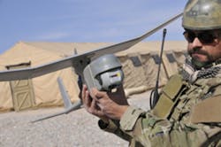
In addition to missile IMU requirements, the growth in unmanned aerial vehicles (UAVs) and autonomous ground vehicles (UGVs) has resulted in related needs such as stabilized camera platforms. A number of examples are provided by the series of unmanned aircraft systems (UAS) and separate sensors available from AeroVironment.
The company’s gimbaled sensor datasheet explained, “… [The] suite of micro-gimbals delivers lightweight, compact visual awareness solutions designed to satisfy …demanding requirements. Each…payload includes a daylight digital camera and an infrared thermal imaging camera that are packaged to provide reliable operation in harsh environments, delivering uninterrupted video imagery.”4
Courtesy of AeroVironment
AeroVironment’s separate gimbaled sensor packages mount on a conventional airplane to provide a stable imaging platform at prices ranging from about $20,000 for a daylight camera with tilt-only positioning to about $50,000 for a larger unit with both types of imaging, a laser pointer, and continuous rotation as well as tilt capability. A similar small stabilized gimbaled payload with forward and side-look cameras is available for the company’s Raven® RQ11B lightweight unmanned aircraft system (UAS) shown in Figure 1.
Technologies
In contrast to gimbaled platforms that maintain a fixed angular position while the structure to which they are attached rotates around them, so-called strapdown systems are directly fastened to the moving structure. Modern electronics and especially MEMS gyroscopes and accelerometers have facilitated good IMU performance while simplifying the associated mechanics and reducing cost.
Gyroscopes
Several nonrevolving types of gyros are available, many MEMS-based and a few laser-based. Although piezoelectric MEMS have been developed, most MIL/Aero MEMS gyros vibrate either as a tuning fork or torsionally. An article in The Draper Technology Digest distinguished between automotive or commercial-grade angular rate sensors—piezoelectric and other low-cost technologies—and those it classified as having tactical performance. According to the article, “Automotive or commercial-grade angular rate sensors perform at several hundred to a few thousand deg/h…. tactical grade performance [is] on the order of 1 to 10 deg/h.”5
As discussed in a Northwestern University mechanical engineering project paper, Draper Labs developed a tuning-fork gyro (TFG) in 1993. Initial performance was adequate for use as an automotive skid-control sensor in anti-lock braking applications. By 1997, 100°/h resolution had been achieved together with much lower input voltage noise.
According to the reference, “In 1999, Honeywell acquired the Draper Lab technology in MEMS gyroscope design…. The HG1700 [IMU] was integrated with MEMS gyroscopes from the Draper laboratory, replacing the ring laser clusters.
These systems functioned similarly to their predecessors with the exception that they could be made smaller at an economical cost. Soon after, the HG1910 was developed with the use of Honeywell-designed gyroscopes, utilizing similar techniques [to those] taken from the Draper laboratories.”6
Vibrating MEMS gyros operate by sensing a reaction to the Coriolis effect. Many different forms of vibrating gyros have been developed to take advantage of different ways in which the Coriolis effect manifests itself. In a TFG, the fork elements experience a force perpendicular to their plane of vibration in response to an angular rate of rotation.
A detailed analysis of the sources of error in TFGs and their mitigation was included in The Draper Technology Digest article. In particular, the authors reported that, “Based on technology developed at Draper Laboratory, Honeywell is delivering HG1900, HG1920, and HG1930 Navigation Systems. After a decade of excellent test data, production quantities now are being realized. In 2004, several hundred systems were delivered for military applications, such as artillery shell and mortar shell guidance.” These typical uses substantiate the need for the HG1920’s large operational range listed as 1,440°/s.6
Facilitated by MEMS and semiconductor technology developments during the last decade, inertial sensor performance and cost have improved to the point that the market is anticipated to grow from about $2.9B in 2011 to $6.9B in 2016. The largest growth is expected in consumer electronics such as cell phones, tablets, and gaming systems. Other significant markets include automotive, industrial, aerospace, military, and medical.7
An indication of the preponderance of MEMS-based solutions is the list of 114 IMUs at http://damien.douxchamps.net/research/imu/. Most devices sense angular rotation in all three axes and only a small number are not MEMS-based.
Gyros that incorporate lasers are primarily of two types: ring laser gyros (LRG) that directly incorporate the laser into the sensor and fiber-optic gyros (FOG) that do not. Both use the Sagnac effect, which basically says that rotation of a closed optical path will affect the interference between two counter-rotating light beams.
An LRG consists of a closed path, usually made from three or four straight sides with mirrors at the corners. Counter-rotating laser beams are produced within the structure and their frequency difference sensed at a point. During the time the structure is being rotated, the distance traveled by one beam will be larger than that traveled by the other, creating a frequency difference: The cavities within which the oppositely directed beams are resonating will appear to have different lengths.
Depending on the rate of rotation, the two wavelengths of coherent light and their beat frequency will change. In an article about LRGs, an example of a Kearfott Navigation and Guidance LRG is given, which outputs a pulse corresponding to each 0.0005° of rotation. The pulse rate is proportional to the rate of rotation. The article also stated that in some of the company’s guidance applications, GPS signals are used to update the LRG data to reduce accumulated errors. The LRGs provide the continuous data needed for navigation, and GPS periodically improves its accuracy.8
FOG devices do not change the actual operating frequency of the laser: In a FOG, the laser is separate from a long, coiled optical fiber. Again, counter-rotating beams are used.
Accelerometers
Courtesy of Colibrys
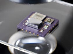
The overall accuracy of gyros and accelerometers involves the signal path as well as the sensor element itself. Figure 2 shows the Colibrys Model MS9000 Accelerometer. As explained on the company’s website, this is a capacitive sensor that uses a bulk micromachined silicon element—the large structure in the lower left of the figure. In addition, the sensor includes a low-power ASIC for signal conditioning, a microcontroller that deals with calibration constants, and a temperature sensor.
A wide range of applications is addressed by MEMS-based accelerometers as suggested by the categories into which Colibrys segments its products:
- Seismic sensing for intrusion detection, earthquake monitoring, and downhole drilling.
- Vibration sensors for modal analysis, structural monitoring, and wind-tunnel use.
- Inertial sensing for attitude and heading reference system (AHRS) and IMUs: long-term accuracy and low drift are key.
- Tilt sensing for safety of large cranes, laser targeting, and platform stabilization.
Today’s Components
Numerous IMU and AHRS examples serve applications requiring varying levels of autonomy and security. Crossbow Technologies (Moog Crossbow since June 2011) was a leader in MEMS inertial sensor development in the mid 1990s. The company released the IMU300 in 1998, the first 6-degree-of-freedom inertial navigation system entirely based on MEMS devices.
In 2003, the AHRS500GA became the first FAA-certified MEMS-based AHRS approved for use by the general aviation market. More recently, Crossbow’s commercial inertial navigation systems product line was sold to MEMSIC. Subsequently, Crossbow concentrated on high-performance defense and security inertial products.
The Moog Crossbow Model GNAV540 ruggedized GPS/IMU is a GPS-aided inertial navigation unit intended for use in ground-based vehicles. It integrates MEMS inertial gyros and accelerometers, a three-axis magnetometer, a GPS receiver, and a 10/100 Ethernet interface. Position accuracy is better than 7.8 m and heading accuracy <1°.9
Cobham Sensor Systems also provides MEMS-based sensors such as the digital air data and solid-state attitude/heading reference system (ADAHRS) with a magnetic sensing unit and outside air temperature probe. The device is intended for use on aircraft and features accurate measurement of position, rate vector, and acceleration.10
Measurement Considerations
For the ADAHRS, angular rates of change up to ±200°/s are within range. The Moog Crossbow GNAV540 also accepts roll, pitch, and yaw changes as large as ±200°/s. Clearly, these systems are designed for manned vehicle navigation, not for the higher rotational rates associated with munitions.
One of the reasons that this specification is important is that strapdown systems determine position and speed by integrating gyro and accelerometer signals. Simultaneously specifying a heading accuracy as well as maximum angular rates of change implies that the integration remains accurate at those angular rates. One may well ask why it shouldn’t.
According to a MicroStrain technical note,11 coning and sculling are two of the undesirable effects that can result from inaccurate integration. Because the airframe motion in general will be nonlinear, large changes in position can occur quickly or over much longer time periods. Only by sampling at a very high rate can you be certain of capturing data at a sufficient resolution to support accurate integration. Coning describes the error that results from inaccurate integration of a high-speed motion such as vibration. If the gyro sampling and subsequent integration are not done with sufficiently fine resolution, the resulting error makes it appear that the axis of rotation is describing a cone in space.
Sculling has a similar cause but relates to the accelerometers instead of the gyros. In this case, the combination of linear and rotational vibration can produce a cyclical velocity error if sampling is at too slow a rate. To minimize both coning and sculling errors, a high sampling rate is needed, but this brings with it high data rates.
MicroStrain’s Model 3DM-GX3-25 AHRS combines MEMS triaxial accelerometers, gyros, and magnetometers; temperature sensors; and an onboard processor running the necessary algorithms. The company claims that this unit avoids coning and sculling errors and, in addition, preprocesses data to reduce the effective data output rate. Sensors are sampled at a 30-kHz rate but data is output at 1 kHz.
Calibration is necessary for any AHRS, and the MicroStrain units are tested and compensated for sensor misalignment, gyro g-sensitivity, and gyro scale factor nonlinearity. The datasheet stated, “All quantities are fully temperature compensated and mathematically aligned to an orthogonal coordinate system.” Gyro drift is claimed to be eliminated by referencing magnetic North and the earth’s gravity and compensating for gyro bias.12
Specifications such as the Moog Crossbow GNAV540’s <10°/h angular rate stability during operation indicate how well compensation has been achieved. This unit’s acceleration bias stability is <1 mg. As good as these specs may be, inertial sensors do drift over time and temperature and generally achieve long-term accuracy by using an external reference. For the GNAV540, it’s the GPS signal. Cobham’s ADAHRS has Pitot and static ports so that true air speed can be directly measured with a Pitot tube sensor.
Further Developments
A Si-Ware white paper presented an ASIC development platform the company had developed.7 According to the paper, there has been a “radical transformation in market and technology over the last five years…. Sensor solutions are trending toward higher complexity with more advanced features and smaller footprint packages, all at lower ASPs.” Some of the company’s claims were supported by Yole Developpement data.
Courtesy of Si-Ware Systems
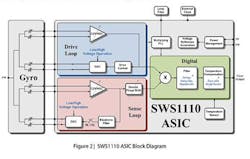
To minimize the risk of codeveloping both a custom MEMS sensor as well as the associated signal-processing ASIC, Si-WARE offers the SW61111 platform based on the company’s SWS1110 configurable inertial sensor interface ASIC. Figure 3 shows a block diagram of the platform. A programming board and plug-in sensor board support MEMS sensor drive and sense evaluation.
No doubt, tactical applications will continue to have special and stringent requirements. Nevertheless, the emergence of sensor development platforms such as the Si WARE SWS61111 is an indication of a maturing industry segment. Increased demand for inertial sensors also will stimulate innovation, perhaps leading to even better price/performance.
References
1. Keller, J., “DARPA seeks to wean smart weapons off GPS with hybrid inertial navigation system-on-a-chip,” April 18, 2012.
2. Keller, J., “DARPA pushes forward with navigation sensor fusion initiative to reduce dependence on GPS,” June 17, 2012.
3. Jackson, T., “Modifying the MARK 6 Guidance System,” EE-Evaluation Engineering, September 2009, pp. 22-28, and October 2009, pp. 12-19.
4. Gimbaled Sensors, AeroVironment, Datasheet.
5. Weinberg, M., and Kourepenis, A., “Error Sources in In-Plane Silicon Tuning-Fork MEMS Gyroscopes,” The Draper Technology Digest, 2007, pp. 42-55.
6. Burg, et al, MEMS Gyroscopes and Their Applications, Northwestern University, ME-381 Project Paper.
7. ASIC Development Platform for MEMS Inertial Sensors, Si-Ware Systems, White Paper, July 2012.
8. Shiner, L., “How Things Work: Ring Laser Gyros,” Air & Space, September 2002.
9. GNAV540 Datasheet, Moog Crossbow.
10. ADAHRS Datasheet, Colibrys.
11. Coning and Sculling, MicroStrain, Technical Note TN-I0019, 2010.
12. 3DM-GX3®-25 Up and North Compensation, MicroStrain, Technical Note TN-I0029, 2012.
For More Information
AeroVironment
Charles Stark Draper Laboratory
Cobham Sensor Systems
Colibrys
Honeywell Precision Sensors
MicroStrain
Moog Crossbow
Si-Ware Systems
About the Author
Comment About the Article
To join the conversation, and become an exclusive member of Electronic Design, create an account today!

Leaders relevant to this article: