Power Grid Energy Storage Testing Part 2
Distributed energy storage (DES) is an enabling technology for the future power grid. Largely composed of advanced electrochemical batteries, DES systems increase the efficiency of large centralized power stations, incorporate renewable energy from solar and wind farms, and improve the reliability and cost of energy provided to consumers. To support the rapid evolution of DES technology, DNV KEMA hosts an energy storage performance testing lab in Chalfont, PA.
Part 1 of this article1 provided an overview of DES technology and current methods for evaluating DES systems at KEMA, and it described the energy-storage data acquisition and control system provided by Bloomy Energy Systems. Part 2 presents typical DES performance specifications and test requirements, DES test scenarios, and performance reports.
DES Performance Specifications
DES performance specifications and test requirements vary considerably depending on the location of deployment, size, and application. Key parameters include voltage, active power, reactive power, and energy. As a representative example, the ratings for the S&C Electric Company’s PureWave® CES System are shown in Table 1.2 Test standards include IEEE 1547.1-2005 Interconnection Testing of Distributed Resources, IEEE 1159-2009 Recommended Practice for Monitoring Electric Power Quality, NEN-EN-IEC 61000-4-30 Electromagnetic Compatibility—Testing and Measurement Techniques—Power Quality Measurement Methods, and American Electric Power’s Functional Specification for Community Energy Storage Unit-Revision 2.2.3
Additionally, KEMA has defined special application-specific tests related to performance, safety, and environmental aspects not currently published in a standard. The end-user application helps KEMA determine the required efficiency, capacity, cycle life, energy density, response time, and rate of charge and discharge.
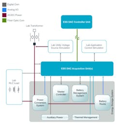
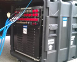
The Energy Storage System (ESS) performance test lab’s test configuration is shown in Figure 1. The Lab Utility Voltage Source Simulator may be used to vary the voltage and frequency supplied to the DES. An adjustable RLC load bank simulates a wide variety of loads. Multiple measurement points from the DES test device, grid, and load simulators are connected to the ESS DAC Acquisition and Control (ESS DAC) Unit(s) with isolation transducers as appropriate. The ESS DAC Control Unit is located inside the lab’s control room.
DES Test Scenarios
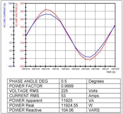
In a recent DES test, the lab transformer was configured for 240-V/120-V single split-phase residential power and applied to the DES test device, and the load bank was adjusted to simulate residential demand. The ESS DSS DAC unit measured the voltage and current of the lab transformer, the DES power-line input terminals, and the load. DC voltage and current were measured from the DES battery, which consisted of multiple cell stacks inside a sealed container. Also, temperature was monitored using four thermocouples located near the inverter, on the top cover of the DES, near the bottom of the DES, and on the top cover of the battery case. The voltage and current waveforms were analyzed to determine the power factor as well as the apparent, real, and reactive power. A snapshot of the data is shown in Figure 2.
DES performance tests include round-trip efficiency, life cycle, and capacity. The round-trip efficiency test procedure involves discharging the DES into the grid from fully charged to fully discharged at rated power and then charging the DES back up to fully charged. The round-trip efficiency is the energy output by the DES into the grid during the discharge cycle divided by the energy input from the grid during the charge cycle. In practice, fully charged, fully discharged, and rated power are all variables defined by the user.
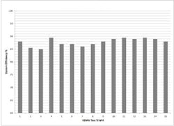
Figure 3 shows a sample of a round-trip efficiency test in which fully charged is 90% state of charge (SOC), fully discharged is 10% SOC, and rated power is 25 kW. The bar graph indicates the calculated efficiency measured by the ESS DAC system for each of 15 trials.
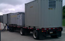
In a recent test of a 1-MW DES designed for renewable integration, the ESS DAC system and a high-power RLC load bank trailer were transported to the DES manufacturer’s facility to perform an onsite acceptance test, as shown in Figure 4. The system was used to measure 3-phase voltages and currents at the source, load, and power conversion system; calculate power; and perform unintentional islanding tests as per IEEE 1547.1.
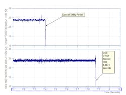
Unintentional islanding is a condition in which power is lost unexpectedly from the grid while the DES is supplying power to that same portion of the grid. The DES is suddenly powering a much larger load than intended. An unintentional island threatens the safety of utility personnel that may be working on the problem that caused the power loss and may damage the DES or other transmission and distribution equipment.
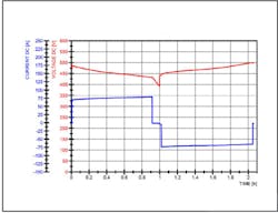
According to section 5.7 of IEEE 1547.1, the distributed resource must detect the unintentional island and cease to energize the circuits within 2 seconds of the formation of the island. This test is based on matching the DES output to a resonant load and measuring the time between the utility power loss and the DES circuit break. As shown in Figure 5, the utility power loss and DES circuit break are measured as voltages across auxiliary contacts.
Report of Performance
The measurement data is imported into NI DIAdem software for offline processing and formatted to generate KEMA’s standard performance report. KEMA issues a certificate of performance for tests that conform to a published standard or a report of performance in accordance with client’s instructions for nonstandard tests. A brief excerpt from a performance test can be found accompanying the online version of this article at www.evaluationengineering.com.
Conclusion
The ESS DAC system from Bloomy Energy Systems executes a variety of functional, performance, life-cycle, and application-specific tests to validate DES specifications for rating, capacity, and efficiency. This system is used by KEMA to evaluate the performance of DES systems against current industry standards, including NEN-EN-IEC 61000-4-30 for power-quality measurements, IEEE 1159-2009 for power-quality monitoring, and IEEE 1547.1-2005 for distributed power resources conformance.
KEMA also uses the ESS DAC system to perform field testing up to any power level and test performance through any application such as renewable integration, peak shaving, and frequency regulation.
KEMA’s ESPT lab and Bloomy Energy Systems’ ESS DAC system are aiding manufacturers and users in safely designing and deploying DES systems for the power grid. DES systems are helping to increase generation efficiency, integrate renewable power sources, reduce carbon emissions, support PEV technology, and improve reliability at the edge of the grid. DNV KEMA and Bloomy Energy Systems will collaborate to add new DES test capabilities as test standards evolve.
References
1. Blume, P., Lindenmuth, K., and Murray, J., “Power Grid Energy Storage Testing, Part 1,” EE-Evaluation Engineering, November 2012.
2. Ratings—PureWave Community Energy Storage System, S&C Electric Company.
3. Functional Specification for Community Energy Storage (CES) Unit, Revision 2.2, American Electric Power, Dec. 9, 2009.
About the Authors
Peter Blume is president of Bloomy Controls. With more than 20 years of experience, he has helped establish engineering best practices through many published articles and presentations and as author of The LabVIEW Style Book. [email protected]
Kevin Lindenmuth is the systems and test development engineer for DNV KEMA. He primarily is involved with battery cell test program development and performing tests in the KEMA-Powertest Battery Test Facility.
Jonathan Murray is the business unit manager for Bloomy Energy Systems, a business unit of Bloomy Controls. Murray also has held positions in systems engineering, project management, and business development. [email protected]


