Test engineers must measure a number of variables to describe the behavior of a device or process. For an electric circuit, acquiring and analyzing the voltage and current signals are straightforward. However, applications that involve nonelectrical parameters such as temperature, pressure, or humidity require a sensor to convert the physical effect into a voltage or current.
Many kinds of sensors have been developed to deal with the wide range of variable types. The LonWorks fieldbus standard enumerates dozens of types of variables and their ranges in a list of Standard Network Variable Types (SNVTs). According to the LonWorks website, “[SNVTs] facilitate interoperability by providing a well-defined interface for communication between devices made by different manufacturers. A device may be installed in a network and logically connected to other devices via network variables as long as the data types match…. A SNVT index is defined for each network variable that is used when defining self-identification for network variables.”1
At a lower level, a sensor description also requires specification of properties such as hysteresis bands, default values, minimum and maximum limits, gain settings, and delay times. By completely defining a sensor’s type and parameters, you should encounter minimal problems when changing a sensor within a LonWorks network. If a replacement sensor has a slightly different range from that of the original, translation is possible.
Industry’s adoption of several largely incompatible fieldbuses is one factor contributing to the number of available sensors and sensor interface adapters. CAN networks within cars have requirements distinct from the FOUNDATION or ProfiBus fieldbuses found in industrial plant automation applications and from LonWorks used in building automation. The interface between a sensor and the network is different in each case even though the underlying sensor technology may be very similar.
Fieldbuses generally replaced the 4- to 20-mA current-output sensors commonly used in older process automation installations. HART is yet another fieldbus technology, but it has the advantage of adding digital communications to existing 4- to 20-mA current loops rather than entirely replacing them. Status, parameter values, measurement values, and diagnostic data can be exchanged between the sensor and receiver by superimposing frequency-encoded data on top of the current signal.
Test applications are less permanent than those involving a fieldbus solution. Industrial automation uses sensor data to monitor and control manufacturing processes so sensors are built into the plant. Although that data also may be used for test purposes, test is not the primary function of the sensors. A car’s onboard diagnostics capability is a good example in which data from the car’s built-in sensors is made available for troubleshooting purposes. Nevertheless, a mechanic still may temporarily require additional test equipment such as a timing light or a compression gage to fully understand a problem.
Sensor Anatomy
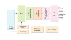
In a test application, sensors provide electrical signals that a data acquisition (DAQ) system can record for later analysis. The block diagram of a pressure sensor (Figure 1) shows the sensing element, some analog signal conditioning, an ADC, further digital processing, and the I2C bus interface. Many sensors also have memory to store test and calibration data. The location of these functions isn’t always obvious although it’s safe to assume that the sensing element is part of the sensor.

Figure 1. Pressure Sensor Block Diagram
Source: STMicroelectronics
Usually, any analysis software resides in the DAQ system. Depending on the type of sensor and DAQ system, the other functions may be part of either. All the functions shown in Figure 1 are part of the STMicroelectronics LPS331AP MEMS pressure sensor with 10,000g shock survivability.
Integrated Identification and Calibration
IEEE 1451 defines the transducer electronic datasheets (TEDS) capability built into many sensors. In addition to the latest calibration data and range values, the datasheet information includes the sensor’s test setup location, model number, serial number, and next calibration date. For large test setups, having the sensor location and type electronically available is a big deal. Before TEDS, you had to physically trace each cable and enter the appropriate calibration constants manually. It took a lot of time, and inevitably, errors were made.
Electrically, TEDS is implemented in two ways. For sensors such as accelerometers that are driven by a constant current source, the Class 1 two-wire interface is practical. As explained in a National Instruments white paper, “Class I transducers include diodes or analog switches with which the multiplexing of the analog signal with the digital TEDS information on the single pair of wires is possible.” For transducers without the necessary internal components, “…the Class 2 interface uses a separate connection for the analog and digital portions of the mixed-mode interface.”2
Integrated Amplifier
One way to categorize sensors is to group those that do not require external power (passive) separately from those that do (active.) A passive sensor, such as a thermocouple, generates an output signal directly from the sensed variable. An active sensor, such as a load cell, is powered by an externally applied source and returns some of that power as the output signal.
Signal conditioning may be applied within the sensor and/or as part of the DAQ system. A good example of integrated conditioning is a piezoelectric (PE) accelerometer, which develops a charge output. Typically, a high impedance buffer will be integrated within the sensor to convert the charge signal to voltage. A low impedance voltage output is much less restrictive than the native charge output and can be cabled over a reasonable distance without error. However, there also are many charge-output accelerometers that require direct wiring with low-noise cable to an external buffer.
Why would you use one instead of the other? According to an Endevco technical paper, the integrated electronic piezoelectric (IEPE) accelerometer can be used in most applications that suit the PE. However, the IEPE electronics limit the temperature range while there are both very high- and low-temperature PE versions. Of course, a very practical reason to use a PE accelerometer is because you have one as well as the required signal conditioning and cabling. If you only need more general-purpose signal conditioning, then the IEPE probably is the better choice.
The technical paper explained that sometimes a piezoresistive (PR) sensor is more appropriate than either IEPE or PE because the PR device has lower sensitivity and is better suited to high shock levels such as experienced in crash testing. Similarly, because of its high output down to DC, the variable capacitance accelerometer often is chosen rather than PE or IEPE models to sense sustained low frequency and low-level motion. Also, an accelerometer’s output may or may not be electrically isolated from the case: both configurations are available.3
Onboard Signal Processing
FUTEK Advanced Sensor Technology provides a range of USB-powered interface modules. The products vary by sampling rate, resolution, input type, and sensitivity but all convert an input to a USB-compatible signal. Types USB210, 220, and 230 offer progressively higher sampling rates and resolution and accept ratiometric inputs up to 1 V/V. Type USB320 supports ±10-V and 4- to 20-mA inputs. Module USB410 is compatible with transducers having a quadrature-encoded output.
The modules are the size of a USB memory stick as shown in Figure 2 and include signal conditioning, an ADC, memory, and the TEDS. The company’s marketing manager Navid Mokhberi explained, “Some purists may dispute that… [a sensor connected to a USB module] may be called an integrated sensor under a strict, traditional definition of the term, but this setup has the same net result… and can be configured, sold, and calibrated as a single system.”
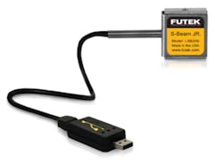
Figure 2. USB220 Module Connected to a Load Cell
Courtesy of FUTEK Advanced Sensor Technology
Digital sensors that include the ADC and output digitized data via RS-232 or RS-485 using various protocols have been practical for several years. According to Mokhberi, “The potential for mass appeal held by the digital sensor [or smart sensor] concept was not fully realized until the development and ubiquity of the USB connection. The USB was a critical precursor to the popularization of digital sensors because it combined several key benefits: high transfer speeds, integrated power, and, perhaps most importantly, customer familiarity.”
If you are addressing a test application and must supply new sensors and DAQ capabilities, FUTEK’s USB approach has advantages. The accompanying SENSIT software accommodates up to 16 sensor channels for simultaneous monitoring and graphing. And, you can perform mathematical calculations on the channels by using the Math Channel function.
Mixed-Signal Processing
In addition to high levels of signal processing made possible by today’s semiconductor processes, the sensor elements themselves are changing thanks to MEMS technology. Although products developed by acam messelectronic are not restricted for use with MEMS sensors, the technologies complement each other well.
acam’s latest devices include analog-to-digital conversion for capacitive or resistive sensor inputs, a 48-bit DSP, associated RAM and programming memory, onboard timing control, a general-purpose I/O port, and both I2C and SPI ports. However, the distinguishing technology on the acam chips is the time-to-digital converter (TDC).
For widely spaced events, you could count cycles of a very stable clock to determine the precise time associated with each event. For much smaller time differences, there’s a practical limit to the clock frequency. As described in an acam white paper, “TDCs use the propagation delay of simple logical gates for fine quantization of time intervals with a typical resolution in the picosecond range. CMOS-based TDCs are fast, highly accurate, and versatile. Since they mainly rely on digital circuitry to accurately measure tiny fractions of time, TDCs have a relatively small analog portion compared to other competing technologies.”4
MEMS capacitive pressure sensors output extremely small capacitance differences. To measure the change in capacitance, the sensor is charged to a precise voltage and then discharged through a known onboard resistance. The time to discharge is measured by the onboard TDC and compared to the time to discharge a reference capacitor through the same resistance. acam’s PICOCAP device handles capacitances from fF through hundreds of nF and supports single-capacitor grounded, single-capacitor floating, differential-capacitor grounded, and differential-capacitor floating configurations as well as resistive sensor outputs.
Digital Output
Honeywell’s Sensing and Control Division uses the digital output terminology to describe several types of sensors. The Model DS digital output pressure sensor features microprocessor-based, internal signal conditioning and micromachined silicon pressure sensor technology. A note in the datasheet explained, “The dual output of both the digital and analog signals allow [sic] flexibility in potential applications where the conventional 0-VDC to 5-VDC output is desired. The digital output replaces the computer interface ADC card with direct connection into your PC RS-232 port.”
The company’s Humidicon digital output humidity sensors support half-duplex operation on the SPI bus. As with the pressure sensor, the output is serial but with a different protocol and physical layer.
Yet another type of digital output is provided by some of the company’s switch products and proximity sensors. Switches can be actuated by temperature or pressure. The output is either an open or closed connection. Proximity sensors that operate on the killed eddy current principle maintain a weak internal oscillation until the RF field near the sensor’s face is disturbed by a metallic object. When enough energy is absorbed by the object, the oscillation amplitude drops, triggering a comparator that drives the output.
Honeywell makes a huge range of sensors, only some of which are suitable for test purposes. Many sensors are designed to be embedded in products so may have PCB mounting pins, low-cost plastic housings, and application-specific connections such as a molded hose barb. Sensors used in test applications usually are more rugged, are intended to be reusable, and include suitable connectors.
Sensor and DAQ System Variety
Although they’re easy to use, USB-powered sensors only are compatible with USB-based DAQ systems. According to NI’s Derrick Snyder, product manager data acquisition, “One of the biggest challenges in most mixed-measurement data acquisition systems is the integration of multiple sensors from varying vendors, of varying styles (intelligent vs. traditional), with varying connectivity, and requiring varying signal conditioning. This sheer variety can make ensuring compatibility and scalability difficult, so system designers should choose a platform that can accommodate the variation that mixed-measurement systems inevitably introduce.”
NI’s C Series platform has available at least 50 NI and third-party measurement-specific modules supporting a number of signal conditioning and span measurement types, channel counts, and kinds of connectivity.
Data Translation’s Ellen Harpin of the Product Marketing Group said the company “offers the capability to connect to various sensors directly via USB and Ethernet devices, eliminating the need for additional signal conditioning. This has not always been the case. Sensors are based on physical properties: metals, crystal, resistance, and capacitance. Previously, sensor inputs had to be amplified, voltage-shifted, and isolated and provided excitation using electronic means to be conditioned for acceptance and compatibility with the measurement devices,” she continued. “Data Translation Direct-Connect modules now contain this necessary signal conditioning inside the module.”
Direct connection is available from Data Translation for many types of sensors including accelerometers, strain gages, thermocouples, and RTDs. The DT9837B USB module shown in Figure 3 provides support for IEPE inputs, including use of a 4-mA current source and AC or DC coupling. The DT9838 USB module handles strain gages and implements TEDS as well as full-, half-, and quarter-bridge completion and bridge excitation. The DT9828 deals with thermocouples and provides both cold junction compensation and analog filtering and also is compatible with USB. The company’s DT8837 Ethernet module has capabilities similar to those of the DT9837 series.
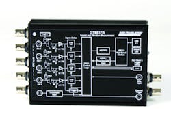
Figure 3. DT9837B Direct-Connect Module
Courtesy of Data Translation
Also addressing USB and Ethernet networks, DATAQ Instruments sells the DI-8B industrial amplifiers that handle the signal conditioning needs of most types of sensors and transducers. The series includes voltage, current, RTD temperature, strain gage, potentiometer input, frequency, thermocouple, and LVDT. In each case, the amplifier module provides 1,000-V input-to-output isolation and 500-V channel-to-channel isolation when used with the company’s DI-718B multichannel DAQ system (Figure 4) with either USB or Ethernet compatibility.
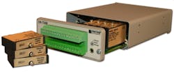
Figure 4. DI-718B Multichannel DAQ System
Courtesy of DATAQ Instruments
FUTEK's Mokhberi described an application that mixed the company’s CSG110 universal strain gage signal conditioner with NI DAQ equipment. “The product being evaluated loosely resembled a piece of Nautilus-style weight-training equipment. The engineer conducting the study needed to simultaneously monitor multiple input and output forces and the various angular displacements at play. These channels were to be related in real time in a virtual instrument (VI) he had created in LabVIEW.
“At the… [time] we first spoke with him, the displacement encoders were already in service and set up to communicate with his VI via an older NIDAQ card. This card did not have a means of applying a known excitation voltage to force sensors…. In this case, the force sensors were paired with CSG110 and set to output a 0 to ±5V signal, which was compatible with the existing NIDAQ card,” Mukhberi explained. “The measurement system that was created allowed the customer to capture dynamic, multidimensional measurements on his existing software platform and allowed him to avoid needing to upgrade his data acquisition card.”
Summary
In most cases, there is no shortage of sensors to choose among. Nevertheless, you may find your options limited depending on the application’s constraints. The requirement to work with an existing DAQ system, a restricted budget, or extreme test conditions could considerably narrow the list of suitable sensors.
Direct sensor connections would appear to be preferable, but separate signal conditioning can provide isolation, excitation, simplified calibration, and translation to a different network protocol. These capabilities ease sensor selection restrictions and could result in a lower overall cost. And, for smaller test systems, it’s hard to argue with the simplicity provided by smart sensors, whether actually integrated or integrated in the FUTEK style.
References
1. “LonMark SNVT and SCPT Master List,” Echelon, Vol. 11, Rev. 2, May 2002.
2. IEEE 1451.4 Standard Overview, National Instruments, White Paper, September 2006.
3. Steps to Selecting the Right Accelerometer, Endevco, TP 327, August 2009.
4. Intelligent ASICs for MEMS Pressure and Humidity Sensors, acam messelectronics, White Paper, December 2012.
For More Information
About the Author
Comment About the Article
To join the conversation, and become an exclusive member of Electronic Design, create an account today!

Leaders relevant to this article: