A New Approach for Multi-Emitter Test Signal Generation

Today’s radar and communications systems face an increasingly crowded and complex spectral environment. The frequency spectrum may include countless RF and microwave emitters—and therefore potential interferers—such as wireless communications infrastructure, wireless networking systems, and civilian radars. Evaluating radar and communications hardware under a variety of signal scenarios can help characterize system performance in the presence of multiple interference signals.
Creating a multiple emitter environment consisting of radar signals and communications signals can involve using multiple signal generators and possibly multiple racks of equipment. It also may include custom hardware and software, which can be expensive. In addition, multiple racks of test equipment can occupy significant floor space which may be difficult to accommodate in some R&D lab environments.
An alternate approach using commercial-off-the-shelf (COTS) test equipment and simulation software can offer benefits both in terms of cost-effectiveness and physical space. One option for creating multi-emitter test signals is to use simulation to model the waveforms and then download them to an arbitrary waveform generator (AWG) to create the physical test signals.
Simulation offers flexibility in being able to model different types of signals such as wireless emitters (LTE, W-CDMA, EDGE, GSM) as well as radar emitters with various kinds of modulation on the pulse. Some signals, however, may be difficult to try to recreate in simulation and better represented by capturing and recording them for playback in the lab environment. An example may be a signal from legacy custom test equipment or a signal that is captured in an operating environment.
A new hybrid approach combines simulated waveforms with captured real-world waveforms to create multi-emitter test signals in the R&D lab environment. The first part of this approach uses a multichannel phase-coherent digitizer to capture, record, and analyze communications and radar waveforms. The recorded waveforms are read into simulation, resampled, and then combined into one waveform. The resulting waveform then is downloaded to one of the channels on an AWG.
For the second part of this hybrid approach, modeled radar and communications waveforms are simulated, resampled, and combined to download the resulting waveform to the other channel on the AWG. The two channels of the AWG then are combined to create a composite multi-emitter test signal consisting of both captured emitters and simulated emitters.
Using a Multichannel Phase-Coherent Digitizer
The test setup shown in Figure 1 is used to capture and record multiple waveforms as well as simulate and create the multi-emitter test signals. The test setup consists of an AXIe chassis with an embedded controller and simulation design software. An eight-channel AXIe-based phase-coherent digitizer is used to capture waveforms of up to 800 MHz bandwidth, and a precision AXIe-based two-channel AWG is used to play back the multi-emitter waveforms.
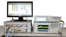
Figure 1. Test Setup with AXIe-Based Digitizer and AWG (left), RF Signal Generator (upper right), and RF Signal Analyzer (lower right)
The RF signal analyzer on the lower right is used to perform wideband downconversion of the RF spectrum from the RF signal generator to an IF spectrum to capture and record with the AXIe-based digitizer. Figure 2 shows the RF spectrum which is to be captured and recorded by the digitizer.
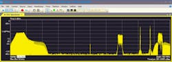
Figure 2. RF Spectrum to be Downconverted, Captured, and Recorded with the AXIe-Based Digitizer
Digital downconversion (DDC) on the digitizer is used to effectively tune and zoom into each center frequency and decimate the digitized data for a given user-defined frequency span. Vector signal analyzer (VSA) software then is used to further resample the DDC-decimated data for modulation-domain measurements. This combination of hardware and software decimation and resampling offers measurement speed advantages over software-only approaches. In addition, the hardware DDC decimation lowers the noise floor to improve the digitizer’s measurement performance.
The downconverted waveform is captured and recorded on different channels and at different center frequencies using the digitizer, then analyzed using the VSA software as shown in Figure 3. The captured and recorded waveforms consist of a radar signal shown on the left, followed by an LTE signal, an EDGE signal, a custom OFDM signal, and a W-CDMA signal. The LTE, EDGE, custom OFDM, and W-CDMA signals are being demodulated to measure their error vector magnitudes. Their constellations and code-domain power (W-CDMA) also are being displayed.
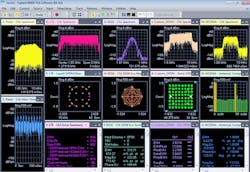
Figure 3. Demodulation Using VSA Software with Multichannel Digitizer and DDC
Playback of the Recorded Waveforms
Once the five waveforms have been captured and recorded on different channels and at different frequencies, they can be resampled and combined into one waveform in simulation and then downloaded to channel 1 of the AWG to play back the signal. Figure 4 shows the simulation schematic to read the five-channel recording into simulation. The multichannel recording is resampled and combined into one waveform which then can be downloaded to channel 1 of the AWG.
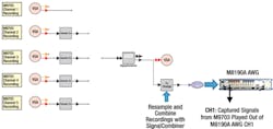
Figure 4. Schematic to Read the Five-Channel Recording into Simulation
The effective time length of the captured and recorded signals is a function of the physical memory of the digitizer and the DDC sample rate. The effective time length of the playback waveform using the AWG is a function of the AWG’s physical memory and the sample rate used.
Simulating Additional Emitters to Playback
Figure 5 shows L-band, S-band, and C-band radar and two additional W-CDMA emitters which are being simulated, resampled, and combined into one waveform. For this example, only W-CDMA emitters were used; however, other simulated emitters such as LTE, GSM, EDGE, and WLAN have been used for similar applications.
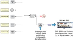
Figure 5. Simulated Radar and Communications Emitters Resampled and Combined to Download to Channel 2 on the AWG
The resulting simulated multi-emitter waveform then is downloaded to channel 2 of the AWG. This capability is not real time since it is simulation-based.
Combining Captured and Simulated Emitters
The resulting multi-emitter test spectrum is composed of both recorded and simulated emitters. Channel 1 is playing back the captured and recorded emitters, and channel 2 is playing back the simulated emitters. A hardware signal combiner is used to combine the outputs of channel 1 and channel 2 on the AWG to create the composite spectrum shown in Figure 6, which was measured using an RF signal analyzer.
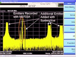
Figure 6. Composite Spectrum from Recorded Signals and Simulated Emitters Measured with an RF Signal Analyzer
Summary
A new capture and playback approach generates multi-emitter test signals using a combination of COTS test equipment and simulation software. Although this capability is memory-based and limited in capture and playback time, it offers flexibility because it utilizes both simulated waveforms and captured real-world waveforms which may be difficult to model. This COTS-based approach also can offer cost and floor-space advantages over multirack and custom test equipment approaches.
Author’s Note: The work shown in this article represents preliminary work in progress.
About the Author
Greg Jue is an applications development engineer/scientist working on aerospace/defense applications at Agilent Technologies. He pioneered combining design and test solutions at Agilent, wrote the design simulation section in Agilent’s new LTE book, and authored application notes 1394 and 1471 on combining simulation and test. Before joining Agilent in 1995, Jue worked on system design for the Deep Space Network at the Jet Propulsion Laboratory, Caltech University.
About the Author
Comment About the Article
To join the conversation, and become an exclusive member of Electronic Design, create an account today!

Leaders relevant to this article: