High-speed-digital test targets physical layer
Vendors offering instruments targeted at the test of serial I/O links and DDR interfaces include Anritsu, Keysight Technologies, National Instruments, Rohde & Schwarz, Tektronix, and Teledyne LeCroy, as described in our January Special Report on the topic. Instruments including oscilloscopes, bit-error-ratio testers (BERTs), network analyzers, and protocol analyzers as well as hardware and software options all may have a role to play.
In this Web-exclusive article, representatives of National Instruments, Keysight Technologies, Tektronix, and Teledyne LeCroy elaborate on high-speed digital test. Particular topics of interest include fixturing and probing and physical-layer test; DUT control, stimulus, and response; de-emphasis; 100G Ethernet; Fibre Channel; DDR test; and solid-state-storage test.
National Instruments
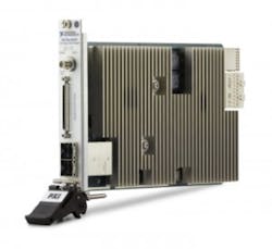
Chris Nunn, a product manager at National Instruments, cited a white paper titled An Introduction to NI High-Speed Serial Instruments as a good resource for additional information on the topic. It covers the emergence of high-speed serial interfaces and application examples involving the PXIe-6591R and PXIe-6592R high-speed serial instruments.
“With the ever-increasing demand for higher data bandwidth, wired interfaces have increased their clock rates and parallelism to keep up. But when the smallest amount of skew between the clock and data lines of a traditional parallel data bus threatens the bit error rate of the interface, serial data links offer a solution,” the paper states. Specific application examples focus on protocol functional test; DUT control, stimulus, and response; high-bandwidth data movement; and link debug and parametric test.
Nunn also specifically addressed fixturing issues. “We’ve chosen to use industry standard connectors for both the PXIe-6591R and PXIe-6592R to ease fixturing and probing issues,” he said. “These connectors include mini-SAS HD connectors on the PXIe-6591R model and SFP+ connectors on the PXIe-6592R model. We also provide a mini-SAS HD to SMA breakout for increased flexibility, and have custom mass interconnect solutions through partners like Virginia Panel Company.”
Keysight Technologies
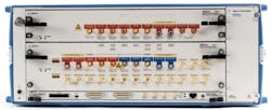
Keysight Technologies also addresses fixturing issues. Ellen Spindler, product marketing manager, commented on the J-BERT M8020A, saying, “For RX test, often compliance fixtures from the standard bodies or customer test boards are used that can be connected with standard cables to the BERT—for example, SMA/SMB cables.
She added, “We provide de-emphasis capabilities on the pattern generators to compensate for losses of the test set up. For RX testing, we offer two new boxes.” First is the M8048A with ISI channels that can be cascaded to emulate a certain loss as defined in the receiver test specification. Second, on the analyzer side, the J-BERT M8020A provides an integrated CTLE to open closed eyes for BER testing.
In addition, Mike Resso, product manager for serial bus testing at Keysight, said, “Automatic Fixture Removal (AFR) is a unique solution that PLTS [Physical Layer Test System] 2014 utilizes to remove fixture or probe effects without the costly fabrication of calibration standards. Other methods such as de-embedding still require the user to supply the S-parameter model of the fixture or probe to be removed. This is a costly and time consuming step that must be done. AFR accomplishes this task simply and easily like no other product inside Keysight or outside Keysight.”
Keysight offers several resources for additional information:
- Master your next PCI Express test with the J-BERT M8020A,
- Master Your MIPI M-PHY Receiver Tests with the J-BERT M8020A,
- Master Your Next USB 3.x Designs with the J-BERT M8020A,
- Introducing the J-BERT M8020A high-performance BERT (video), and
- Keysight M8195A AWG: The Digital and Arbitrary Signal Generator (video).
See also www.keysight.com/find/plts.
Tektronix
Chris Loberg, senior technical marketing manager at Tektronix, summarized his company’s offerings for high-speed digital test:
- comprehensive test solution for LPDDR4,
- test solution for HDMI 2.0 compliance testing and debug,
- 40GBASE-CR4 debug and automated compliance solution,
- enhanced IBIS-AMI S-parameter modeling support for Tektronix oscilloscopes,
- 40 Gb/s high-performance BERT for datacom and long-haul testing,
- new BERTScope model to address 100G optical receiver test requirements, and
- MIPI mobile protocol decode solutions for oscilloscopes.
He also cited several relevant application notes:
- Electrical Verification of DDR Memory,
- Physical Layer Tests of 100 Gb/s Communications Systems,
- Basics of Serial Data Compliance and Validation Measurements, and
- Correlation of Measurement and Simulation Results using IBIS-AMI Models on Measurement Instruments.
Loberg specifically commented on datacom test with respect to emerging standards such as 100G Ethernet, 32G Fibre Channel, EDR InfiniBand, and OIF CEI. All, he said, require multiple lanes of traffic at greater than 25 Gb/s per lane. “The trend of increasing bandwidth over multiple lanes of traffic is expected to continue as standards advance to 400 Gb/s and 1 Tb/s,” he added. “Tektronix supports these test challenges with performance instruments and high-speed components designed to provide best-in-class broadband frequency coverage and signal integrity.”
He continued, “Tektronix high-speed test solutions outperform narrow-band alternatives that were originally designed for RF applications and later adapted to accommodate these emerging standards. This is because Tektronix components were designed by Picosecond Pulse Labs with an emphasis on serial data test and for use in measurement engineering labs.”
He said the Tektronix high-performance PatternPro multichannel BERT systems and DSA8300 oscilloscopes, coupled with broadband components, provide engineers with the tools necessary to perform comprehensive standards compliance testing and product characterization from 4 to 40 Gb/s per lane.
As for fixturing issues, Loberg said Tektronix works in conjunction with Nexus Technology to offer LPDDR memory component interposers. “EdgeProbe interposers,” he said, “are designed for the demanding mechanical constraints required by mobile designs while socketed interposers are available for ease of use, reusability, and component swapping. In addition, probing solutions for P7500 Tri-mode and P7300 differential high-bandwidth probes combined with a wide variety of interposers provide access to hard to reach signals for all flavors of DDR and LPDDR memories.”
He added that the P7600 Series TriMode probes and the MSO/DPO70000DX and DPO/DSA70000D Series oscilloscopes are designed to deliver low system noise levels. High sensitivity, he said, is critical for being able to make accurate measurements on low-amplitude signals. The P7633A offers a full 33-GHz bandwidth to the probe tip, and remote head design connectivity allows placement of probe amplifier close to the circuit being measured.
“TriMode probing enhances productivity by enabling differential, single-ended, and common-mode measurements with a single probe setup,” Loberg added. “Connecting a probe to the device under test can be a time-consuming activity, especially if the probe has to be set up differently to make all the necessary measurements. TriMode probing improves productivity by reducing setup time because only one setup is needed to make the three different types of measurements.” Switching between differential mode, single-ended mode, and common mode is as easy as a press of a button, he said.
Teledyne LeCroy
Robert Mart, product manager at Teledyne LeCroy, claimed several DDR-test-related firsts for his company in addition to separating reads and writes, as covered in the January Special Report. The company’s DDR Debug Toolkit, he said, permits simultaneous analysis of four different measurement scenarios. “Each measurement scenario,” he said, “has a choice of a signal to be analyzed as well as selecting read or write for that signal. For example, it is simple to set up a comparison of system performance between read and write burst operation across multiple DQ lanes. A built-in reference scenario facilitates performance tuning and optimization tests to observe changes in system behavior.”
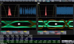
In addition, he said, the toolkit enables users to view up to 10 eye diagrams simultaneously, perform eye mask testing, and measure eye parameters such as height, width, and opening to obtain a quantitative understanding of system performance.
The toolkit also supports DDR jitter analysis. “Because DDR signals are bursted,” Mart said, “conventional serial-data analysis packages will not do the job for jitter analysis on DQ, DQS, and address signals. Jitter parameters including Tj, Rj, and Dj are calculated across all active measurement scenarios. For a deeper understanding of the jitter distribution, traditional displays include TIE histograms, TIE track, and bathtub curves.”
He added, “DDR Debug Toolkit includes a roster of parameters that are specific to DDR test, making it easy to quickly configure insightful measurements for validation, characterization, and debug. Users may display up to 12 configurable measurements while simultaneously analyzing all of them across all active measurement scenarios. For each measurement, users may display statistics such as min, max, mean, and measurement count.”
Roy Chestnut, product manager at Teledyne LeCroy, addressed other topics, including solid state drives. “As SSD technology has evolved,” he said, “storage developers are migrating to PCIe-based SSD storage. Teledyne LeCroy has introduced new PCIe storage analysis tools to help companies with this new test learning curve.”
He added, “The USB-IF has introduced a new 3.1 specification that includes support for speeds up to 10 Gb/s. Our Voyager M310 analyzer and exerciser platform provides support for all speeds up to and including 10 Gb/s.”
Addressing still other topics, Chestnut said, “Enablement of interoperability testing for the 16GB Fibre Channel links has become a hot customer issue. Now that data centers are incorporating new fabrics, specifically for 16GB FC, the need for inter-operational testing is becoming more pervasive. Testing between HBAs, switches, and servers is increasingly important to ensure the highest end-to-end throughput and minimal latencies. Additionally, the emergence of 40GE fabric links is creating a need for line rate analysis. The legacy use of virtual taps/probes is proving inadequate due to the characteristics of the line rate transmissions, the disparity of connections and types (that is, fibre vs. active/passive copper), and the inability to actually ‘see’ what is on the wire.”
He continued, “As serial data speeds have increased, the need for ‘dynamic RX/TX equalization’ has become more prevalent in the high-speed specifications. As test tools are placed in line with the devices under test, this equalization can be affected. Most tools today use a limiting amplifier implementation to ‘capture’ the signal. This limiting amplifier can have adverse effects on the bus. Teledyne LeCroy has shifted to a T.A.P.3 probing mechanism which implements limiting amplifier technology.”
With respect to probing and fixturing, Teledyne LeCroy’s PCI Express product line offers a variety of probe systems, including interposers to capture data traffic across a card-connector interface, mid-bus probes designed to capture traffic between components on one PCB, and multi-lead probes that can be attached directly to exposed traces on a PCB. Customers can also acquire Teledyne LeCroy technology to create their own probing solutions, Chestnut said.
“With the SierraNet product line as well as our SAS/SATA product lines,” he said, “the passive T.A.P.3 front-end design inherent in our platforms provides no corrective or intrusive effect on the high-speed fabrics under examination. One key use is analysis of the auto negotiation and training sequences now implemented in 16GB FC and 10/40GE over copper. Soon, with the advent of Gen 6 Fibre Channel and 100/400GE fabrics, the use of corrective technologies like FEC and the mandatory use of training sequences will require front-end probing solutions that allow the engineer to not only capture and analyze these parameters, but ensure that the observational tools do not obfuscate the native bus conditions. In short, the analyzer should not become part of the fabric under test.”
He continued, “Another important tool in Teledyne LeCroy’s arsenal is the Virtual Probe software option. Virtual Probe enables viewing of waveforms as they would appear in circuit locations other than the probing point, and in circuit configurations different from the configuration actually used for the measurement. It is very useful in circumstances where a user wants to understand the characteristics of signals at a point in the circuit where a physical probe cannot be placed, such as inside of a chip package or at the end of an interconnect that does not physically exist. Users can remove effects caused by elements such as fixtures that will not be present when the DUT is in its final configuration, or add the effects of a device that is to be included but for which only an S-parameter model exists.”
To use Virtual Probe, a customer creates a model of the circuit to be analyzed with a simple user interface. For each block of the model, the user indicates whether or not the Virtual Probe output should include or remove the effects of that block. For differential measurements, the customer indicates the probe used so that the probe’s loading effects can be removed. Then the user identifies the physical location of the probe as it takes the measurements as well as the position of the Virtual Probe that outputs the waveform as it would appear at that location.
“A common application for VirtualProbe is mid-bus probing of DDR interfaces,” Chestnut said. “Part of the issue in such cases is removing the probe loading, which the software does by default. But there is a larger problem when probing at the termination of a signal path at a receiver’s input. In such applications, the signal must be acquired at a point before the signal path terminates at a receiver. However, the probing point may be affected by reflections from an imperfect termination. To correct this issue, which is commonly caused by the input capacitance of the receiver chip, our Virtual Probe@receiver (VP@Rcvr) math operator is provided as a component in the EyeDoctor II software package. Without need of S-parameters for the DUT, VP@Rcvr creates a termination model that can be applied for reflection compensation. It is important to note that the outputs from the Virtual Probe software, in which loading effects have been removed, can serve as input to the DDR Debug Toolkit software.”
Teledyne LeCroy offers several white papers and application notes for more information:
- A Practical Guide to 12Gb/s SAS Probing Methodologies,
- Guidelines for Using Teledyne LeCroy PCI Express Gen3 Multi-lead Probe,
- Probe Design for SuperSpeed Protocol Analyzers, and
- LAB WM789 – Compensating for Imperfect Receiver Terminations: Using the VirtualProbe@Receiver Math Operation to Eliminate Reflections.
About the Author

Rick Nelson
Contributing Editor
Rick is currently Contributing Technical Editor. He was Executive Editor for EE in 2011-2018. Previously he served on several publications, including EDN and Vision Systems Design, and has received awards for signed editorials from the American Society of Business Publication Editors. He began as a design engineer at General Electric and Litton Industries and earned a BSEE degree from Penn State.
Comment About the Article
To join the conversation, and become an exclusive member of Electronic Design, create an account today!

Leaders relevant to this article: