IJTAG interoperability brings value to chip and board engineers
The newly approved IEEE 1687 standard—Internal JTAG, or simply IJTAG—is changing the way tools companies like ours think about interoperability. For example, IJTAG interoperability is tremendously valuable at both the chip and circuit-board levels because of the re-use of embedded instrumentation intellectual property (IP). Moreover, when chip- and board-level IJTAG tools feature two-way or back-and-forth interoperability, all of the tools in the flow become more powerful than they could be on their own. Call it the power of synergy.
Interactively applying both board-level and chip-level IJTAG tools to a complex system design means that the design is validated with advanced diagnostics only available because of the power of synergy. Ultimately, designers can quickly pinpoint the cause of problems either in the chip or on the circuit board.
IJTAG’s network of instruments
Development of the IJTAG standard began a number of years ago because engineers needed a better way to access, manage, and control instruments embedded in silicon. At the time, more and more instruments were being integrated into complex systems-on-a-chip (SoC) and other not so complex devices. These embedded instruments were and still are the most effective way to characterize and verify the functionality of chips.
Unfortunately, many of these instruments could not talk to each other, and, depending on where the IP came from, each instrument might have its own access method. In addition, portability was sorely lacking. Instrument IP could not be easily redeployed in another chip design without redesigning the IP for the new chip. In other words, embedded instruments were difficult to use for engineers.
The IJTAG standard solves these and other problems by specifying an on-chip network, which is described by the standard’s Instrument Connectivity Language (ICL). In addition, IJTAG defines a standardized interface to instrument IP as well as an operational instrument language, Procedure Description Language (PDL). These aspects of IJTAG simplify and enhance how engineers apply embedded instruments and ensure the portability of not just the instruments themselves, but also the operational vectors associated with each IJTAG instrument, another time saver for engineers.
Why interoperability matters
Interoperability between IJTAG tools at the chip level, such as Mentor’s Tessent IJTAG solution, and those applied to circuit boards, like ASSET’s ScanWorks platform, is much more than a convenient way to transfer data between tools. Bi-level, bi-directional interoperability is a powerful benefit to both chip and board engineers for a couple of reasons: First, it ensures that the instrument IP developed to validate or test a chip design can be re-used on a circuit board design, reducing costs and speeding the product to market faster; and second, the two-way feedback loop between chip and board tools means that the entire tool flow is now capable of advanced diagnostic that can isolate the root causes of design problems in chips or on boards. In other words, this IJTAG tool flow ends the guesswork in determining whether the problem is in the chip or on the board.
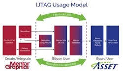
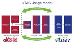
Figure 1 illustrates an IJTAG tool flow from instrument insertion in chips all the way through to circuit board assembly.
The flow begins with Mentor’s Tessent automation inserting and verifying the chip’s IJTAG and JTAG resources. JTAG is needed because the chip’s JTAG Test Access Port (TAP) will be used to access the IJTAG on-chip network of instruments. IJTAG is not limited exclusively to JTAG as its access method, but at this time JTAG is the only mechanism supported by the approved IJTAG standard. Other access methods may be added to the IJTAG standard in the future.
The Tessent automation flow supports automatic insertion into a design’s RTL or gate-level netlist. The inserted IJTAG resources include both embedded instruments as well as a hierarchical access network enabling access to any instrument from a common chip-level access point. The Tessent automation also supports both retargeting as well as merging of PDL commands for multiple IP blocks. Commands retargeted to chip pins can be translated to automatic test equipment (ATE) pattern formats or to Verilog for simulation. Chip-level PDL patterns are also supported by Tessent SiliconInsight for interactive debug.
Following insertion and simulation, the chip design is often deployed on field programmable gate arrays (FPGA) where the silicon can be emulated and tested in hardware. The tests generated previously at the simulation stage are applied again to verify the integrity of what will become the on-chip IJTAG network as described in ICL as well as the instrument-specific operational processes as described in PDL. This is followed by typical silicon testing and validation on ATE systems.
At the emulation and ATE test and validations stages is where the interoperability between Tessent and ScanWorks becomes critical. ScanWorks can use the same instruments inserted by Tessent to validate, test, and debug a circuit-board design. In addition, the interoperability of our tools makes it possible for the board-level data captured by ScanWorks later in the flow to be fed back earlier into the Tesset tools at the silicon simulation and validation stages.
SoCs simply cannot be adequately validated until they have been fully tested and validated at the board-level. Problems uncovered by ScanWorks can be traced back to the silicon, or they can be attributed to a flaw in the board design. The huge advantage of this board-level feedback is that it will isolate problems in either the chip or the board design, ending the finger pointing between chip and board engineers. The feedback loop from ScanWorks to Tessent gives chip designers the chance to correct flaws before the chip is mass-produced. Of course, board-level flaws detected by ScanWorks can also be corrected.
This IJTAG flow culminates in board manufacturing where ScanWorks is able to utilize the IJTAG instruments in a SoC to validate and test circuit boards on the assembly line.
Synergistic interoperability
The ability of chip- and board-level IJTAG tools to work together increases the effectiveness of the entire IJTAG flow from chip design validation all the way through to board test in system manufacturing. The two-way feedback loop—forward and backward—enabled by this interoperability is essential for rapidly identifying and isolating the root causes of design problems, resulting in the timely delivery of new systems to market.
To share our experience and expertise with IJTAG, ASSET InterTech and Mentor Graphics are sponsoring a series of educational workshops in major cities in North America, Europe and Asia. Click here for more information.
About the authors
Stephen Pateras is product marketing director within Mentor Graphics Silicon Test Solutions group and has responsibility for the company’s ATPG and DFT products. He received his Ph.D. in Electrical Engineering from McGill University in Montreal, Canada. He can be reached at [email protected].
Tim Caffee is a founder and vice president of Design Validation and Test at ASSET InterTech. He obtained a B.S degree in Mathematics and a B.S. degree in Computer Science from Old Dominion University, Norfolk, VA. He can be reached at [email protected].
About the Author

Rick Nelson
Contributing Editor
Rick is currently Contributing Technical Editor. He was Executive Editor for EE in 2011-2018. Previously he served on several publications, including EDN and Vision Systems Design, and has received awards for signed editorials from the American Society of Business Publication Editors. He began as a design engineer at General Electric and Litton Industries and earned a BSEE degree from Penn State.

