Increased Insight Through Innovative Technology
How does your scope answer this question: What’s wrong with this signal? Typically, that’s the question users want to ask, but it’s not always easy to make a scope understand what you want it to do. Because oscilloscope controls affect vertical sensitivity, horizontal sweep speed, and several trigger modes, some translation generally is needed.
When we asked scope manufacturers the same question, they responded with a range of answers. Teledyne LeCroy’s Chris Busso, senior product marketing manager, emphasized the increased vertical resolution in the company’s HDO high-definition oscilloscopes. With 16 times the resolution of typical 8-bit instruments, these scopes should help users find small signal faults more easily. LeCroy DSOs also feature the WaveScan search and analysis tool, which you can program to look for up to 20 criteria such as rise time, nonmonotonic edges, and runts in waveforms.
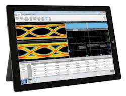
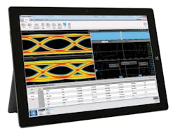
Triggering was at the top of a list of Tektronix scope capabilities provided by Chris Loberg, senior technical marketing manager at the company. In addition, he included the new asynchronous time interleaving technology available in the recently launched DPO70000SX Series scopes with up to 70-GHz bandwidth. And, on the software side, DPOJET is Tek’s package that addresses jitter and timing issues to help determine the root cause. DPOJET is key to the various communications-standards testing Tek scopes can perform (Figure 1).
Courtesy of Tektronix
Triggering also was the topic addressed by National Instruments’ Christian Gindorf, senior product manager. He discussed the open FPGA architecture used in the company’s PXIe 5170/71R scopes, which “… allows users to define their own custom triggers in hardware to help pinpoint elusive anomalies in the waveform. The power of the FPGA is leveraged … by giving the user complete access to the oscilloscopes’ triggering architecture by allowing customized algorithms to be implemented in the trigger circuitry.”
Keysight Technologies’ Daniel Bogdanoff, product manager, was in no doubt when he replied, “The most important feature for top-down faultfinding and debugging is waveform update rate. The higher the waveform update rate of an oscilloscope, the higher the likelihood of seeing a glitch or error in the waveform.” Several Keysight datasheets quote 1,000,000 waveforms/s update rate. Bogdanoff also mentioned the company’s Zone touch trigger that allows users to graphically define a complex trigger condition on screen.
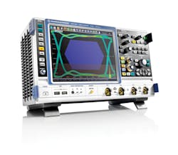
Richard Markley, oscilloscope product manager at Rohde & Schwarz America, agreed that waveform update speed was critical, explaining that, “many times, not knowing there is an issue is [a customer’s] biggest fear.… The less time the scope is working on processing and the more time it is seeing the signal, the more likely you are to find infrequent events.” The company’s RTO series DSOs achieve 1,000,000 waveforms/s update rate for the analog input channels.
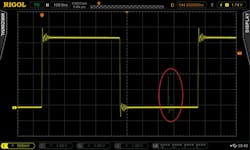
UltraVision technology, which involves both a special chipset and associated software, is key to achieving up to 180,000 waveforms/s update rate in Rigol Technologies’ scopes with bandwidths from 50 MHz to 1 GHz. Chris Armstrong, director of product marketing and software applications at the company, said, “… With the capability to test waveforms vs. a pass/fail mask or a standard trace on thousands of data frames at a time, the onboard waveform analysis features save the engineer considerable time pinpointing their underlying problem. Once the glitch or signal has been analyzed and correlated with logic signals, users can then utilize the embedded source channels to emulate and verify individual signals within the system” (Figure 2). An optional Arb is available on selected models.
Courtesy of Rigol Technologies
Nevertheless, update speed is not the entire answer. R&S’ Markley also discussed the need for both time- and frequency-domain capabilities. He said, “Issues may be more easily seen in the frequency domain than in the time domain, but often to … see them you need to be able to process the time-domain signal into the frequency domain quickly. Using hardware to do both digital down-conversion and calculating the spectrum of a signal greatly increases the chances of finding those elusive events.”
A scope’s history function was one of the features Yokogawa’s William Chen, product marketing—high frequency instruments, mentioned. He said, “The history feature solves the issue of how to quickly isolate the problem waveform from all the previously acquired waveforms …. Using the history search function, users can quickly isolate, analyze, and precisely categorize abnormal waveforms without needing to carefully configure complex triggers.”
Chen also commented on the benefits of built-in serial bus triggering and analysis, features found in many scopes. For example, GWInstek’s Roger Lee, marketing and service department, said, “Serial bus functions help users utilize the GDS-2000E or GDS-1000B [scopes] to observe waveforms, trigger signals, and analyze low-speed serial buses (I2C, SPI, UART, and CAN/LIN). These types of communications [buses] often are used in automotive applications.”
Rather than attempting to choose the most important among a scope’s features, Trevor Smith, business development manager at Pico Technology, said, “PicoScope provides good general-purpose capability, including decoding for many serial standards, automated measurements, and acquisition and display modes that are optimized for tasks such as glitch capture through to waveform streaming for ultradeep waveform analysis and unattended system monitoring applications.”
Although all scope vendors acknowledge the importance of a wide range of capabilities, one scope will perform at a higher level than another in certain applications depending on which aspects the manufacturer has emphasized and how they have been implemented.
Enhanced Capabilities
Power
Many user applications have such specific characteristics that suites of scope capabilities have been developed to address them. Rigol’s Armstrong listed power analysis as a key application for the company. It is addressed by adding the UltraPower Analyzer Software option to either the 2000A or 4000 Series. The option comes complete with a deskew board so users can accurately align current and voltage probe timing. Typically, voltage and current probes have very different bandwidths and delays, which, if not corrected, cause the power waveform to be in error. The software includes standard tests for power envelope and efficiency.
Also related to power, LeCroy’s Motor Drive Analyzer (MDA) is a specially adapted HDO8000 12-bit resolution DSO. The company has a long history of producing scope-based analyzers for special applications such as serial data and disk drive analysis. With eight input channels, the MDA accommodates three phases of voltage and current as well as a couple of control lines, allowing more complete signal correlation. An additional 16 digital channels are optionally available, allowing concurrent torque, position, or further drive signal acquisition.
Although the MDA includes a user-configurable table of power-related measurements—real, apparent, and reactive power; power factor; phase angle; efficiency; voltage; current; and motor mechanical quantities—the overall accuracy is limited to about 1% by the scope’s performance. In contrast, dedicated power analyzers typically feature 16 to 18 bits of resolution and 0.05% accuracy. Of course, these instruments also have limited bandwidth and sampling speed.
High definition
Nicolet Instruments pioneered 12-bit scopes in the 1980s and 1990s. These scopes frequently were used in biomedical experiments because the wide dynamic range afforded by 4,096 digitizing levels allowed researchers to accommodate waveforms with unknown DC offsets yet still capture sufficient detail.
All Nicolet scopes used high-resolution ADCs as do today’s LeCroy HD4096 instruments to achieve the quoted resolution. However, many DSP-based techniques have been developed to enhance the performance of the much lower cost and faster 8-bit ADCs commonly used in DSOs. If a signal is repetitive, averaging successive acquisitions works well to reduce noise. One bit of resolution is added for every factor of four in the number of acquisitions: x4 = 1 bit, x16 = 2 bits.
For the majority of signals, which are not repetitive, averaging acquisitions doesn’t work. Instead, successive groups of points in sufficiently oversampled data may be averaged. This approach does increase the resolution of a single acquisition, but at the expense of both lower bandwidth and a lower output sampling rate.
As noted in a previous oscilloscope special report, “Rather than averaging successive blocks of samples, averaging can be done over the first N points, then over the N points from sample 2 to sample N+1, then from sample 3 to sample N+2 and so on. This approach has two effects. First, it shortens the acquired data record by N points. Second, it maintains the original data rate. This means that peaks appear where they should rather than possibly being offset by N (fast) sampling intervals as can happen in boxcar averaging.
“A moving average is a type of FIR filter with equally weighted taps. A LeCroy application brief discussed the advantages of using a different filter tap weighting that trades slightly less improvement in noise reduction against much better frequency response characteristics. Specifically, the LeCroy ERES FIR filter tap weighting implements a shape similar to an FFT windowing function—nearly unity in the center but tapering off toward zero at the edges.
“The bell-shaped filter characteristic in the time domain has an equivalent Gaussian shape in the frequency domain. The end result is that Gibbs ringing is eliminated. The same degree of smoothing and resolution enhancement can be achieved as with a boxcar average, but the number of taps must be increased.”1
Markley at R&S discussed the approach taken in the company’s RTO DSO to enhance resolution. He said, “… [We use digital filtering that eliminates] the drawbacks of averaging and high resolution. Because it is also done in hardware prior to our digital trigger, the trigger can see the higher resolution data and trigger on it …. By [achieving] up to 16 bits of vertical resolution, this can greatly enhance the capability to see small signal details that may have a big impact on the device under test.”
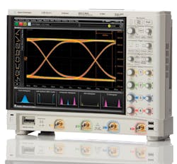
Courtesy of Keysight Technologies
Both Keysight’s 9000H and the newer Infiniium S-Series DSOs are capable of 12-bit resolution. The 9000H uses an 8-bit ADC and DSP techniques to improve resolution. The S-Series scopes (Figure 3) have 10-bit ADCs and offer 12 bits in hi-res mode. Noise has been considerably reduced in the newer models. For example, on the 10-mV/div range with 1-GHz bandwidth, the S-Series AC rms noise floor is 110 µV compared to 181 µV in the 9000H. Similar improvements have been made at all attenuator settings.
Pico Technology’s 5000 Series DSOs provide extensive speed/resolution trade-offs. As explained on the company’s website, “The PicoScope 5000 scopes have a significantly different architecture in which multiple high-resolution ADCs can be applied to the input channels in different series and parallel combinations to boost either the sampling rate or the resolution.” The result is an 8-bit to 16-bit range of resolution and a corresponding range of sampling rates from 1 GS/s to 62.5 MS/s, respectively.
Standards compliance tools
As stated on the R&S website, “Jitter measurements are required for characterization and debugging of fast clock and data signals. Serial high-speed data interfaces such as USB 2.0, LVDS, HDMI, or PCI-e require a special approach for jitter measurements as they use an embedded clock signal as [the] time reference. Therefore, clock data recovery (CDR) is required to extract the frequency and phase information of the embedded clock out of the data signal.
“With the option R&S RTO-K13, clock data recovery is done directly in hardware and real time. This enables triggering on the embedded clock as well as fast histogram and eye-mask testing on high-speed serial data signals with embedded clock.” The company’s Markley added, “Because eye patterns are statistical in nature, doing the clock recovery in hardware greatly increases our chances of finding outliers and infrequent events that a software-based CDR may miss.”
A very large number of serial bus standards are supported depending on the particular scope model. Serial triggering and decoding for low-speed buses are included as standard on many scopes. The more specialized communications buses and aviation buses, such as MIL-STD-1553 and ARINC-429, generally are options. As Tek’s Loberg explained, “Serial bus decoding tools enable the engineer … to identify where control and data packets begin and end as well as identify subpacket components such as address, data, CRC, etc.”
LeCroy’s DDR Debug Toolkit extends the company’s serial-data analysis capabilities by correctly computing DDR jitter even though the signals are bursted. Jitter parameters including Tj, Rj, and Dj are calculated across all active measurement scenarios. Time interval error (TIE) histograms, TIE track, and bathtub curves are displayed.
Measurements and masks
Mask testing was mentioned by a few companies (Figure 4). Teradyne’s Randy Oltman, instrument product line director, said that “for well-known or expected behavior, limit and mask tests can provide a simple go, no-go test. A unique capability of Teradyne’s [ZT Series] instruments is automatic mask generation, which uses a golden waveform to automatically create the upper and lower limits of a test mask.” The mask testing in some Keysight and R&S models is hardware accelerated, speeding up manufacturing and statistical analysis.
Courtesy of Rohde & Schwarz
In general, mask testing occurs after an acquisition has been completed. Waveform match triggering also performs limit testing, but on the fly before acquisition. The user-defined FPGA in NI’s software-designed scopes allows the user to create a custom trigger solution. As the company’s Gindorf explained, a specific example is a trigger that “… continuously monitors the signal acquired by an oscilloscope and is able to detect a specific signal shape without any dead time. The unique nature of the waveform match trigger is the capability to customize trigger limits in hardware, where other solutions can only provide this level of customization in a software trigger solution. This is useful for acquiring very infrequent glitches in a signal that otherwise would demand a very long acquisition and measurement time.”
Measurements have been available on DSOs for many years, but they have proliferated, and some unusual ones have appeared. For example, Oltman said that more than 30 general-purpose time-domain measurements are built into the company’s ZT-Series scopes. In addition, and much less common, a number of frequency-domain measurements such as SFDR, THD, SNR, and SINAD also are provided.
Purchasing considerations
It’s not surprising that all scopes do a good job of acquiring and displaying waveforms given the maturity of the oscilloscope market. But many scopes offer greater value by also including extensive trigger, measurement, and analysis capabilities. However, fundamental trade-offs exist that govern the mix of features within any one model. For example, high-bandwidth direct-sampling scopes are expensive. If you have a small budget but need high bandwidth, you might consider renting a suitable scope. Or, you may be able to use a much lower cost scope with equivalent-time sampling if your signals are repetitive.
The way in which a feature has been implemented may or may not be appropriate for your application. Some scopes feature a high waveform update rate but only for short acquisitions. High resolution can be accomplished in many ways, each with significant implications. And, not all options are compatible with all scopes from a particular manufacturer. Sometimes, it’s a matter of speed: There’s little point in trying to use 10G Ethernet compliance software on a 100-MHz scope. In other cases, marketing decisions may restrict the availability of options for a particular scope.
Because so many variables influence the answer to what’s wrong with this signal, the best way to choose a scope is to evaluate it for a reasonable period of time with your own inputs.
Reference
- Lecklider, T., “Resolving Finer Detail,” EE-Evaluation Engineering, July 2013, pp. 8-12.
