Being turned-on to switching
Although there are many types of RF/microwave switches, not all are commonly used in test systems. As noted by David Owen, business development manager at Pickering Interfaces, “Most test and measurement applications prefer the use of broadband switches so they can be used at all frequencies up to the maximum frequency of the switch. From this perspective, mechanical switches—electromechanical relays and coaxial relays—have highly desirable characteristics.”
Marvin Test Solutions’ (MTS) Mike Dewey, director of marketing, had a similar conclusion. He said, “For RF applications, we continue to use very small footprint reed relays. For general-purpose ATE RF applications where a range of performance parameters is needed (current carry and DC resistance as well RF performance), we find reeds offer the best choice.”
Dewey continued, saying that “FET switches still have too many limitations in terms of performance—DCR, operating voltage range, current carry, etc.—to be a good choice for ATE general-purpose RF applications.”
Pickering’s Owen agreed. He said, “Those [switches] based on FETs have the advantage of faster operation and infinite life within their operating envelope but typically are more limited on power handling and are used at frequencies below 10 MHz.” He concluded, “PIN diode switches have more restrictive frequency coverage and tend to be used only for applications with a much higher minimum frequency. They are not common in general-purpose test systems. MEMs have so far had very limited success because of the high cost and modest power handling, especially when hot switching. MEMs remain a niche technology for test systems.”
Cytec’s CEO, Nick Turner, divided switch technologies into two groups: solid-state and electromechanical. Electromechanical relays (EMRs) are a mature technology that offers a wide range of packages, connectors, and options including latching operation, termination, and indicators to show which state a relay is in. On the downside, because they are mechanical, EMRs wear out and must be replaced after a few million cycles—1E6 cycle-life is typical with some relays quoting up to 1E7.
Turner further divided solid-state into two types. One is in the form of application-specific ICs intended to replace small, PCB-mounted EMRs or to allow the design of more complicated switch products at a lower cost and with better features. He said, “The technology has improved over the years to the point that these offer very good options for replacement of mechanical parts but they tend to … work well only within the applications they were designed to handle.”
He continued, “The second group of solid-state switches was basically designed to replace packaged EMRs. They are provided with RF connectors and a control connector and offer similar specifications to canned EMRs but with much faster switch speeds and much longer life expectancy. While there may be limiting factors such as the inability to switch lower frequencies, handle large amounts of power, or remain connected in power loss situations, these switches are a very good option to replace slower mechanical relays with low life expectancy.”
Universal Switching’s Jesse Woolridge, sales engineer, concurred, adding, “Typical solid-state switching will impact or limit the RF parameters of a signal in some way. Whether it is due to the switch itself or supporting circuitry, FET and diode switches typically will be optimized for a specific bandwidth or application parameters. However, solid-state switch components tend to be very small and are often utilized in compact and highly featured switches that include signal distribution, mixing, gain adjustment, or just about any integrated feature one would require.”
RF switching
Depending on the reference you consult, the demarcation between RF and microwave frequencies can vary considerably. Most sources agree that frequencies in the few-hundred-megahertz range are called RF, but the upper limit can be as high as a few gigahertz. RF frequencies extend downward from these somewhat arbitrary limits. Technologies that have worked well at lower RF frequencies have steadily been improved to increase the number of higher frequency applications that they can address.
Cytec’s Turner mentioned 3 GHz as an important limit. Turner said, “Once we get above the 3-GHz range, it becomes more challenging because the designs require more exotic circuit layouts, different board materials, and better RF shielding. For many of our applications that do not require large quantities of switch modules, it is more cost-effective to use existing boards with mechanical relays or buy packaged solid-state switches from vendors that already make these products at an affordable price. But the trend is definitely moving toward solid-state solutions as the technologies improve.”
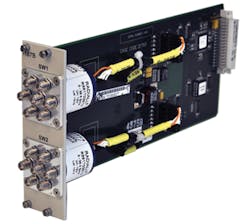
The eight-channel Model 7446 interrupt switch from Cytec uses solid-state 50-Ω coaxial switch modules to control serial data lines with rates up to 1.2 Gb/s and frequencies to 1 GHz (Figure 1). This is a 50-Ω single-ended system that also can be used differentially in a 100-Ω environment. A built-in FPGA controller allows you to interrupt the data stream in 10-µs increments. As stated in the datasheet, “The interrupted wire may be opened, shorted, or terminated in either direction…. The unused path is always terminated for low noise and crosstalk.” In addition, commands may run interrupt patterns of different times on individual lines.
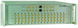
Courtesy of Cytec
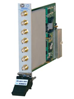
Pickering’s Owen also cited 3 GHz as being significant. He said, “High-frequency EMRs above 3 GHz find it difficult to compete with coaxial solutions…. They are typically expensive and hard to integrate into a switching system. Reed relays with high-frequency claims tend to be restricted to SPST forms, which cannot easily be integrated into a switching system. For that reason, we offer 3-GHz EMR solutions and 6-GHz solid-state (CMOS)-based solutions [such as the Model 40-881 50-Ω SP6T terminated 6-GHz multiplexer] shown in Figure 2. Higher frequencies are supported through a range of coaxial relay solutions from DC to 6 GHz and upwards to 65 GHz.”
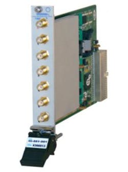
Courtesy of Pickering Inerfaces
Universal Switching’s SLM32 L-band matrix is an example of a large array based on gallium arsenide (GaAs) technology that accommodates frequencies from 950 MHz to 2,150 MHz or 850 MHz to 2,450 MHz with an extended-bandwidth option. Available in either a nonblocking fan-out (SLM32) or combiner fan-in (SLM32(i)) version, the matrix can be configured to be any size from 4×4 to 32×32 in increments of one input and/or output.
Emphasizing reliability, the matrix features built-in continuous diagnostics and a design that isolates failure of an input or output card to only that channel. In addition, redundant hot-swap power supplies are included as standard, and redundant system control interfaces are optionally available.
Improved switching speed was one of the factors influencing National Instruments’ development of the PXIe-2542/3/4 family of DC to 6.6-GHz, high-density, FET-based RF multiplexers. As the company’s Mike Watts, product marketing engineer—modular instruments, explained, “High-volume production test applications within the mobile and semiconductor industries place exceptional demands on switching systems to maximize uptime, throughput, and signal integrity…. The short relay operate time combined with NI’s onboard hardware scanning and triggering engine allow these switch modules to rapidly communicate with high-performance RF instruments, removing the software overhead associated with traditional scan lists and improving test throughput by up to 50%.”
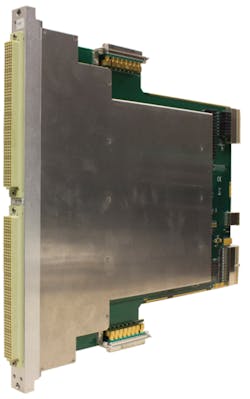
Courtesy of Marvin Test Solutions
MTS has developed the GX7016 switching subsystem that can be configured for specific applications by changing the mix of plug-in cards. The GX6192 HF switch card shown in Figure 3 combines a 16×16 matrix with (16) 1:12 multiplexers, and up to 18 cards can populate a single GX7016 system. To achieve >100-MHz bandwidth, signals must be input via 16 coaxial connectors that are separate from the MAC Panel 6U SCOUT receiver.
Microwave Switching
Coaxial relays
Many test applications with frequencies higher than a few gigahertz use coaxial switches. As VTI Instruments’ Tom Sarfi, director, product management and support, commented, “For most of the applications we target in EW, radar, and telecommunications test, the bandwidth and isolation requirements essentially drive the selection of the switches. In the vast majority of these applications, coaxial relays do not trade off on the key specification parameters…. MEMS and FET switches are of increasing interest and have definite appeal for the wireless communications market as they aren’t prone to the mechanical failures over life that the coaxial relays can experience.”
Members of the company’s EX7000 Series of box-based microwave switching products each contain a relay driver board and an LXI LAN interface board. Up to 72 high-current drive outputs are available to control a number of coaxial relay modules. The EX7000 Series is designed to drive Keysight Technologies coaxial relays from DPDT transfer switches through SPnT multiplex switches. The chassis come in 1U, 2U, and 4U heights, addressing a wide range of applications.
Typically, a coaxial switch wears out electrically because of contact deterioration before it stops functioning mechanically. Debris caused by rubbing between parts of the switch as it opens and closes a circuit contributes to shortened coaxial relay life. As described in a Keysight application note, two types of coaxial relays have been developed. In one of these, the so-called frictionless relays, a rigid jumper bar is pushed against two contacts to complete a circuit. The contact resistance tends to deteriorate as the number of switching cycles increases because debris can accumulate on the contact surfaces.
Well before a switch becomes permanently degraded, repeatability can be affected. It’s desirable for a switch to have a low resistance when closed, but often it’s just as important that the resistance is constant from one switching cycle to another. When used as part of a test setup, a switch with a nearly constant resistance minimizes measurement uncertainty.
Keysight has developed coaxial relays that allow a small wiping action between the jumper bar and the contacts. Because the wiping action cleans the contacts on each switching cycle, the insertion loss repeatability error for these switches can be guaranteed to be <0.03 dB. In addition, the wiping action helps to maximize the number of switching cycles that can be completed with the switch parameters remaining in spec.
Radiall makes coaxial relays as well, but of the frictionless type. To reduce debris generation and buildup on contacts, the company has developed the RAdiall Modular System for Electromechanical Switches (RAMSES) technology. Rather than use guide pins to ensure accurate jumper bar positioning, guidance is provided by flexures located outside of the switch cavity. The company claims that this approach reduces contact deterioration so much that switches made using RAMSES typically achieve 1E7 operations.
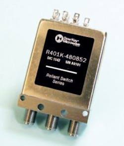
Courtesy of Dow-Key Microwave
Also claiming 10 million cycle life are Dow-Key Microwave’s recently introduced Reliant coaxial switches (Figure 4). Whether the switches are frictionless or use a wiping action is not stated. Nevertheless, 0.03-dB repeatability is guaranteed from DC to 26.5 GHz. When the SPDT model is used in cold-switching applications, 150 W at 3 GHz can be handled, but this drops to 2 W when hot-switching CW signals. Reliant switches operate over a -25°C to +75°C temperature range and up to 15,000-ft. altitude. The switch is offered with latching actuators, optical position indicator, and SMA connectors.
NI’s Model PXI-2797 40-GHz 6×1 terminated 50-Ω multiplexer uses a Radiall R584 series relay and guarantees the mechanical operating life to be at least 2E6 cycles. The electrical operating life is not specified. Like many EMR-based switch modules, the PXI-2797 includes nonvolatile flash memory that records the total number of switch operations. Although operating conditions greatly influence EMR contact life, counting the number of operations is the first step in preventative maintenance, which minimizes disruptive unexpected switch failure.
Courtesy of Astronics Test Systems
Coaxial relays often are directly mounted to a switch module’s front panel, as shown in Figure 5 for the Astronics Test Systems Model 1260-167AH/BH microwave switch plug-in for the company’s 1256 switching mainframe or the 1260-100 Adapt-a-Switch carrier. As stated on the datasheet, “User connections are made directly to the relay SMA connectors at the front panel of the plug-in, eliminating cumulative losses and induced noise.”
This switch features frictionless Radiall relays, and the datasheet states, “The relays used in this card have highly reliable and repeatable operations with a 10 million-cycle life span (25 million typical).” Nevertheless, the actual specification guarantees one million operations at full rated load and does not quote repeatability.
Passive intermodulation (PIM)
At high power levels, the small nonlinearities in a switching system can become important. The level of PIM associated with a switch is measured by the same kind of two-tone intermodulation test that is used for any nominally linear component. As discussed in a Keysight application note, “PIM is an unwanted signal created by the mixing of two or more RF signals, caused by nonlinearity of the passive components in the RF path, such as antennas, cables, or connectors. [The] PIM product is the result of high-power tones mixing induced by ferromagnetic materials, junctions of dissimilar metals, metal-oxide junctions, contaminated junctions, and loose RF connectors.”1
For a sealed microwave coaxial relay, many of these possible problems must be minimized by design. Both Dow-Key Microwave and Keysight offer a number of -160-dBc low-PIM switches suited for base-station applications. In addition to the switch construction contributing to low PIM, tightening connectors to the correct torque level also is critical. Astronics provides a specially designed deep-slotted socket for a ¼-inch socket drive to be used with the company’s 1260 Series switch modules.
Solid-state switches
For some applications, PIN diodes offer an alternative to coaxial relays when switching time is important. Compared to the typical 15-ms switching time for a coaxial relay, PIN diodes switch in about a microsecond and have unlimited life. There also are downsides including a significant minimum frequency, high insertion loss, and video leakage.
For example, Keysight’s Model 85331B PIN diode switch handles signals with frequencies from 45 MHz to 50 GHz, but the maximum insertion loss increases from 2 dB at 500 MHz to 15.5 dB at 50 GHz. A related application note includes details about video leakage—the name given to the amount of the control signal that feeds through to the switch output.
The application note stated, “Most switches contain video leakage; the magnitude can be as low as a few mV to as high as 3 V in a 50-Ω system. FET or hybrid switches generally offer lower video leakage, a few mV while PIN diode switches have higher video leakage due to innate design requirements. In PIN diode switches, the RF and DC biasing share the same path. When control voltage is applied to turn the switch on and off, a current surge will be generated.”2
To put the amount of video leakage into perspective, the application note cited the example of Keysight’s Model P940x PIN diode switch with 500-mV pk-pk video leakage, which was said to be very low for this kind of switch. In comparison, FET switches may have 10-mV pk-pk video leakage. Tests on very sensitive receivers, for example, could cause damage if the switching transient (video leakage) is too high.
Of course, if video leakage isn’t critical and your minimum frequency is high enough, PIN diode switching can be a good solution. VTI’s Sarfi commented that the company had used PIN diode switching in a RF/signal routing and distribution system for a military customer’s missile test application.
Making an informed choice
As comments and examples from vendors have demonstrated, coaxial relays have few drawbacks other than limited life, relatively large size, and slow switching speed. Electrically, they continue to set the performance level that other technologies strive to achieve. Nevertheless, there are many application solutions that can use solid-state switching to advantage.
Inconsistencies found when comparing comments about solid-state switching made by various vendors simply reflect preferences for different technologies: Pickering uses CMOS at 6 GHz. NI uses FETs at 6.6 GHz. And, Universal’s L-band matrix is based on GaAs switches. Some vendors don’t use any of these, preferring conventional EMRs. Comparing the characteristics of several switch types, both EMR and solid-state, to the switching system’s requirements helps to identify those best suited to the application.
References
- Innovative Passive Intermodulation (PIM) and S-parameter Measurement Solution with the ENA, Keysight Technologies, Application Note 5991-0332EN, December 2014.
- Understanding RF/Microwave Solid State Switches and their Applications, Keysight Technologies, Application Note 5989-7618EN, September 2014.
About the Author
Comment About the Article
To join the conversation, and become an exclusive member of Electronic Design, create an account today!

Leaders relevant to this article: