Automotive conducted disturbance testing
Ensuring automotive conducted immunity is one-fourth of the overall EMC job. Thoroughly covering all aspects of automotive EMC involves all four combinations of conducted, radiated, immunity, and emissions over a wide range of signal types and frequencies.
Because a conventional car is electrically isolated, conducted EMI generally relates to interference caused by internal systems that affects other electronics within the car. In addition, car electrical systems must withstand disturbances to the battery system such as sinusoidal noise and starting drops as defined in ISO and SAE pulse 2b and pulse 4 and other starting profiles specified by each manufacturer. EV and hybrid immunity testing is not covered in this article.
Automotive pulse conducted immunity
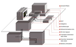
Figure 1 shows a typical conducted immunity test setup based on Teseq equipment. The transient generator block comprises a number of modules depending on the types of pulses required. Importantly, it also includes a built-in coupling decoupling network (CDN) that adds the pulse waveforms to the battery voltage and allows an oscilloscope to monitor the result. The split between tests classed as battery disturbances and those that are considered EMC-related is evident in Figure 1, in which the NSG 5600 function generator is a separate module. This instrument generates battery-related disturbances and is shown connected to the battery simulator.

Courtesy of Teseq
Load dump
One of the more severe conducted disturbances results from disconnecting the battery while the alternator continues to output current. This doesn’t happen under normal operation, but cable corrosion, poor or loose connections, and intentional disconnection are possible causes. As described in ISO 16750-2:2010, the associated load-dump pulse (designated pulses 5a and 5b [clamped] in ISO and SAE standards) has an amplitude from 79 V to 101 V in a 12-V system and lasts from 40 ms to 400 ms. A 2006 paper stated, “The amplitude of the pulse depends on the alternator speed and on the level of the alternator field excitation at the moment the battery is disconnected. The pulse duration depends essentially on the time constant of the field excitation circuit and on the pulse amplitude.”1
The pulse has a risetime between 5 ms and 10 ms and a much longer fall time. Two types of generators have been available—one that drives a pulse shaping network from energy stored in a capacitor and the other that amplifies an input signal. The main difference is that the shape of the output from the amplifier-based system is much less sensitive to the size of the driven load. As the load resistance decreases for the stored energy/pulse shaping approach, the pulse duration becomes less.
Today’s generator designs must meet the requirements of ISO 7637, ISO 16750, and SAE J1113 as well as those of the various car manufacturers, each of which has one or more of its own standards. Interestingly, rather than considering load dump as an EMC event, ISO 16750 groups it with battery-related issues such as voltage reduction during engine starting. However, Japan’s JASO A1, B1, and D1 pulse specifications all call for a 1-µs pulse risetime, and Mercedes Benz MBN 284 part 2 as well as SAE J1455 require 100-µs risetime. Large amplitude pulses with these risetimes can affect EMC by causing radiated emissions and crosstalk within a wiring harness.
The emtest LD 200N load dump generator is an example of a generator that, in addition to the basic pulse shape, can create a clipped pulse to simulate the action of a car’s transient protection circuitry. Source impedance is selectable from 0.5 Ω to 38 Ω in 0.1-Ω steps, and pulse duration can be extended to 1,200 ms. Risetime of <1 µs is supported.
Teseq’s LD 5550 load-dump generator is described in the datasheet as using an active pulse shaping circuit, and as the manufacturer claims, “… [is the] only generator capable of suppressed pulses without affecting the pulse width.” However, there also is a comment at the beginning of a Teseq automotive test brochure, stating, “… all Teseq’s automotive transient generators utilize capacitive discharges into pulse shaping networks, yielding compliant, high energy transients.”2
Compared to the emtest instrument, the LD 5550 risetime is no faster than 90 µs. The emtest datasheet lists the pulse repetition rate specifications of various manufacturers—for example, Ford ES-XW7T CI 240 (AB-Version) “3 pulses every 30 seconds”—but does not list the unit’s capabilities. Teseq’s LD 5550 specification states pulse repetition as “15 s to 600 s in 0.1-s steps” and notes that pulse repetition depends on pulse energy. Both Teseq and emtest are part of AMETEK’s Compliance Test Solutions group.
HILO Test’s PG 2804 is a load-dump generator with selectable source resistance (0.5 Ω, 1 Ω, 2 Ω, 4 Ω, and 8 Ω) and pulse duration (50 ms, 100 ms, 200 ms, 400 ms) and adjustable charging voltage. As stated in the datasheet, “PG 2804 includes generation of pulse 5 [a and b]. It is designed to be connected to the power supply interface of the CAR-TESTER…. The software program CAR-remote permits the PC control of the generator via Ethernet and fiber optic and allows the standardized documentation according to IEC 17025 and the evaluation of test results.”
The company’s CAR-TEST-SYSTEM 14 provides pulse waveforms 1, 2a, and 3. As an option, an electronic power supply can be added that, according to the datasheet, “… serves as an adjustable voltage source to the electrical simulation system … for slow switching pulses 2b, 4 sine between, and [load dump] pulse 5 a and b.” HILO products are available from Reliant EMC.
Pulse generators
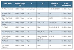
In addition to electrical system tests related to starting, load dump, and the surge from connecting a battery, automotive electronics must withstand transient interference generated when various loads are switched. Similar to the designation of pulse 5a/5b to represent load dump pulses, several other pulse shapes have been defined as shown in Table 1 for a number of standards. P1 is a transient caused by disconnecting the battery from inductive loads. P2 simulates transients caused by interruption of current in a device connected in parallel with the DUT due to the wiring harness inductance.
Courtesy of Teseq
Significantly different signals generally require separate generators. Teseq’s NSG 5500 actually is a collection of several transient generators and the LD 5550 load-dump module. The MT 5511 generator simulates all of the Table 1 pulses and provides higher test voltages, additional impedances, and more pulse widths. The company’s FT 5531 generates 100-ns and 150-ns fast transients corresponding to type 3a/3b pulses with burst frequency programmable from 1 kHz to 100 kHz in 100-Hz steps. Like the pulses in Table 1, these transients also are created by switching and influenced by the characteristics of the wiring harness but are distinguished by being at least 10x faster and up to 600-V in amplitude.
A Teseq frequently-asked-questions file3 addressed improvements to the FT 5531 in line with ISO 7637-2:2011 pulse width tolerances and included Figure 2, an overlay of 200 100-ns 100-V pulses terminated in 50 Ω. The oscilloscope measurement columns list statistics for amplitude, width, and risetime. The column labels include the scope’s designations P1, P2 … P6 to indicate separate measurements. These labels do not refer to ISO pulse types P1, P2, etc. The included histograms are guides to how each variable is distributed but need to be used with care. For example, the pulse width distribution appears to be narrow because there is a larger variation in values than for the pulse risetime, which appears broader.
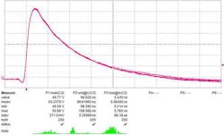
Courtesy of Teseq
Japan’s Noiseken Noise Laboratory also manufactures an automotive transient surge simulator, Model ISS-7650, which generates load-dump pulses. It uses a capacitive discharge approach in compliance with the ISO standard. Like Teseq’s LD5550 and emtest’s LD 200N generators, it too provides type 5b clipped waveforms. The pulse repetition period is from 30 s to 999 s, and from one to 999 pulses can be programmed. Pulse duration is selectable from 40 ms, 100 ms, 200 ms, 350 ms, and 400 ms while both output resistance and output voltage are programmable in small increments. Risetime is set to the nominal 10 ms -5ms/+0 ms, and a 60-V/30-A CDN is built in.
The Noiseken range includes the Model ISS-7630 pulse 3a and 3b transient generator and the Model ISS-7610 pulse 1 and 2a generator as well the Model BP4610 function generator/transient surge simulator with a built-in 60-V/10-A DC to 150-kHz amplifier. The ISS-7602 rack provides a convenient place to house the various units, but the company doesn’t appear to offer an integrated conducted immunity test system as a standard product. Noiseken equipment is available in the United States from Shinyei Corporation of America.
Keysight Technologies has taken a different approach: replaying captured transients from real car electrical systems. Almost any oscilloscope can be used to capture transients although Keysight’s M9210A 10-bit and InfiniiVision 9000 H-Series 12-bit scopes can improve fast transient resolution. Once captured and downloaded to your PC for editing, the files can be used to drive an arbitrary waveform generator and power amplifier or, as described in a Keysight application note, the company’s N6705A DC power analyzer. The N6705A can reproduce waveforms defined at up to 512 points and provide up to 600 W of power.4
Although the N6705A uses only 512 points, it employs a point/dwell model that assigns a separate dwell period to each amplitude point. An algorithm is described in reference 4 that converts previously captured, equal-time-sampled data to the point/dwell format. The algorithm compresses long acquisitions by grouping together consecutive samples with amplitudes varying by less than a user-determined threshold value. Some fine waveform detail will be lost, but the major features will be retained.
Finally, a Littlefuse application note5 that covers the use of the company’s TVS diodes to suppress automotive transients noted that, although a vehicle’s alternator typically uses zener diodes to protect against load-dump surges, this may not be enough. The paper reviewed tests using a 2,200-W TVS diode with both the ISO 16750-2 requirement for 10 load-dump pulses applied at 1-minute intervals and the ISO 7637-2 specification of a single pulse, concluding that the device limited voltage to about 24 V in either case.
Automotive RF conducted immunity
Rather than requiring a series of specially defined pulses, automotive RF conducted immunity testing uses a signal generator, power monitoring capabilities, an amplifier, a directional coupler, and control software. AR RF Microwave Instrumentation provides these functions in the Model CI00401A 150-W RF conducted immunity system covering the frequency range from 100 kHz to 400 MHz. Accessory kit TK3000 includes all the attenuators, injection probes, calibration fixtures, calibration resistors, and termination resistors necessary for automotive testing.
Frankonia also offers a self-contained system with similar capabilities to address conducted RF immunity tests from 10 kHz to 400 MHz according to IEC/EN 61000-4-6, ISO 11452-4, MIL-STD-461 E/F, CS114, and SAE-J1113-2. The CIT-10 has a 75-W amplifier; the directional coupler needed to measure both forward and reflected power is optional. Frankonia products are available in the Unites States from Ophir RF and Reliant EMC.
In addition to automotive-specific pulse generators, emtest manufactures the CWS 500N1.3 continuous wave simulator for conducted RF immunity testing from 10 kHz to 400 MHz. As well as the built-in 1-kHz 80% amplitude modulation that satisfies a large number of car company specifications, this generator provides a 2-Hz 80% AM signal to test medical appliances and a 1-Hz PM signal with 50% duty cycle to test safety equipment such as fire alarms. The current monitor measures frequencies up to 1 GHz, allowing the instrument to be used at higher frequencies with an external amplifier.
Teseq’s NSG 4070 is a versatile multifunction EMC immunity test system for both conducted and radiated testing. The 9-kHz to 1-GHz signal generator output is available for use with external amplifiers or can be connected to an internal 20-W, 30-W, or 75-W amplifier with 150-kHz to 230-MHz frequency range. Remote control from a PC is supported, but the instrument has sufficient built-in routines to be used as a standalone test system. Several diagrams in the datasheet make it clear how the device can be used with various CDNs, clamps, and injection probes.
ETS-Lindgren’s EMGen RF Signal Generator Model 7003-001 is used with the company’s EmCenter modular test system and provides both a low-frequency 9-kHz to 230-MHz output as well as a high-frequency 80-MHz to 6-GHz output. Although the EmCenter can include power meter modules, a separate RF amplifier is required. And, in common with other manufacturers, a separate CDN or current clamp is required to couple the signal to the DUT wiring.
Conclusion
Where automotive conducted RF immunity testing is relatively straightforward and equipment from many manufacturers can address it either completely or partially, electrical disturbance and transient testing is specialized. Unless you are regularly involved in this type of testing, renting the more unusual equipment should be considered. The RF immunity test instruments are general-purpose in nature and can be used to satisfy other types of test requirements.
References
- Spriessler, R. and Fuhrer, M., “Load Dump Pulses According to Various Test Requirements: One Phenomenon—Two Methods of Generation—A Comparison,” Automotive EMC Conference, 2006.
- Automotive electrical disturbances: transient emissions, immunity, and battery simulations, Teseq, January 2013.
- Schlup, C., “Technical Information, FAQ, FT_5531,” Teseq, August 2012.
- Automotive ECU Transient Testing Using Captured Power System Waveforms, Keysight Technologies, Application Note 5989-7763EN, July 2014.
- Automotive Circuit Protection using Littlefuse Automotive TVS Diodes, Littlefuse, Application Note, 2015.
For more information
About the Author
Comment About the Article
To join the conversation, and become an exclusive member of Electronic Design, create an account today!

Leaders relevant to this article: