Lead’s toxic effect on people has been known for a long time, and as a safeguard, many restrictions on its use have been implemented. The current problems with the water supply in Flint, MI, underscore how serious environmental contamination by lead can be.
Predating the Flint situation by several years and addressing the use of lead and several other hazardous substances, the EU’s Restriction of Hazardous Substances (RoHS) Directive took effect on July 1, 2006. In addition to lead, the allowed amounts of mercury, cadmium, hexavalent chromium, polybrominated biphenyls, polybrominated diphenyl ether, and four types of phthalates also were severely limited.
As stated in the RoHS Directive, “The purpose of Directive 2002/95/EC on the restriction of the use of certain hazardous substances in electrical and electronic equipment is to approximate the laws of the Member States on the restrictions of the use of hazardous substances in electrical and electronic equipment and to contribute to the protection of human health and the environmentally sound recovery and disposal of waste electrical and electronic equipment.”
Lead is a component of solder used in the manufacture of electronic equipment of all kinds, and as a result of RoHS adoption, traditional tin-lead (Sn-Pb) solders have been replaced by lead-free (LF) versions. Nevertheless, there are some exemptions, mostly based on the lack of long-term reliability data for LF solders and the possible impact solder-joint failure could have in critical applications. For example, Sn-Pb solder may be used in servers, storage and storage array systems, network infrastructure equipment for switching and transmission, and network management for telecommunications. NASA, aerospace vendors, and the military also continue to use Sn-Pb solder. A 2015 PowerPoint presentation by Indium’s senior technologist Ron Lasky estimated that about 25% of soldered assemblies and solder-plated parts still use Sn-Pb solder.1
A very practical side of RoHS is the need for manufacturers to maintain only one bill of materials for a given product. Except for the equipment going into critical infrastructure applications, most electronic devices and their component parts use LF solder. Even those groups currently allowed to use Sn-Pb solder realize that most of the COTS equipment they purchase probably has been manufactured with LF solder.
The Pb-free Electronics Risk Management (PERM) Council published a report in 2014 outlining the risk LF solder posed for high-reliability applications. PERM members are representatives from companies that also are IPC members, such as Boeing, BAE Systems, Airbus, and GE Aviation, and all are deeply interested in the LF solder issue. IPC originally was the Institute for Printed Circuits and today uses the same IPC initials with the tag line “Association Connecting Electronic Industries.”
The report concluded that LF electronics … “continues to be a concern of the aerospace, defense, and high-performance products industries primarily due to the lack of data and knowledge to thoroughly categorize performance under harsh service conditions.”2
NASA too has been active, completing a Technology Evaluation for Environmental Risk Mitigation (TEERM) project in 2005 to establish a body of knowledge about LF solder.3 As reported on the TEERM projects website, “Currently there is not enough high-reliability (IPC Class 3) data to understand how lead-free materials will behave under the harsh environments of space applications. There are too many variations with lead-free materials including board finishes, part finishes, and solder alloys. Process and performance reliability is tied to the selection of lead-free materials for specific applications. Further complicating the issue is the fact that process and performance reliability can vary greatly for the same product supplied by different vendors….”
Chemistry
Sn-Pb solder
Reviewing how conventional Sn-Pb solder works is a good place to start. If you’ve ever used a cheap soldering iron, you know how quickly the unplated copper tip begins to degrade. It’s actually dissolving in the molten solder. Microscopically, the tin in the solder is forming intermetallic compounds (IMCs) with the copper—typically Cu3Sn and Cu6Sn5. This thin layer bonds to the rest of the solder. Other than the IMC layer, the composition of the bulk solder in the joint is similar to the original solder but with a little less tin and a little added copper. The lead in the solder remains in solution and does not form IMCs.
As stated in an article about IMCs encountered in soldering,4 “Intermetallics generally are crystalline and chemically stable structures…. They do not really react with anything else once they have formed. If you have ever looked at a fractured solder joint, you may have noticed that the fracture likely took place right at the interface between the intermetallic layer and the bulk solder.” Even for traditional Sn-Pb solder, a weak joint will result if the IMC layer is too thick or too thin—conditions related to soldering temperature and time.
LF solder
An early LF solder adopted about 1999 was SAC387, with the approximately eutectic composition Sn3.5Ag0.9Cu. Keeping the silver content low has been shown to reduce the size of the Ag3Sn IMC platelets, improving the joint strength. This is important because larger platelets contribute to fractures along the IMC boundary.
Around 2006, SAC305, Sn3.0Ag0.5Cu, slightly reduced the silver content. From about 2007 to the present, SAC105, Sn1.0Ag0.5Cu, with even less silver, has been preferred. Unfortunately, SAC105 melts at 225°C compared to 219°C for SAC305. On the other hand, SAC105 performs better in drop shock (DS) tests than SAC305, and the lower silver content makes it cheaper.
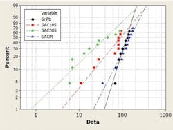
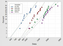
Thermal cycling (TC) tests over the 0°C to 100°C range have proven that SAC305 performs better than SAC105, which in turn is better than Sn-Pb. However, results are mixed for higher temperatures. Further confusing the issue, small amounts of a fourth “dopant” material can make a big difference both for TC and DS tests. For example, SACm, 98.5Sn<1Ag0.5Cu0.05Mn, has better DS performance than either SAC105 or SAC305 and matches SAC305 for TC performance over the -40°C to 125°C range. According to Lasky, “The mechanism for the improved performance is attributed to a stabilized microstructure with a uniform distribution of IMC particles.”1
An Indium research paper5 described several SACm test results, “… [Low-Ag SAC] … compromised temperature cycling performance, [and] therefore was not acceptable for high-end applications in which temperature cycling performance is critical.” For example, your cell phone doesn’t have to cope with repeated -40°C to 125°C excursions on a daily basis, but this environment commonly is encountered in space applications.
The paper continued, “In this study, low-Ag SAC alloy doped with manganese, called SACm, was evaluated against eutectic Sn-Pb, SAC105, and SAC305 in the JEDEC drop (Figure 1), dynamic bending, -40/125°C temperature cycling (Figure 2), and 1-Hz/2-mm cyclic bending test…. The low-cost SACm achieved a better drop test performance than the low-Ag SAC alloys plus the desired thermal cycling reliability of high-Ag SAC alloys.”
Courtesy of Indium
cycling performance
Courtesy of Indium
Tin whiskers and plague
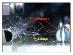
Pure tin coatings, often used on component leads, can grow tin whiskers (Figure 3),6 which are known to cause electrical shorts. Although the phenomenon can’t be 100% eliminated, it is relatively easy to control. According to Lasky, Texas Instruments has used nickel plating with a thin palladium coating topped with gold to protect the nickel and minimize detrimental IMC formation—nickel dissolves in tin much more slowly than copper, so the resulting IMC is thinner. Other suppliers recommend Sn-Bi, Sn-Cu, and SAC solders for BGA package leads.
Courtesy of NASA GSFC
Tin whiskers are thought to be caused by stress buildup within the tin. A clue to understanding how this arises comes from the composition of the Cu3Sn and Cu6Sn5 IMCs that tin forms with copper. Because more copper atoms diffuse into the tin than the other way around, the tin is stressed. At the Sn-Cu interface, the copper is being depleted, and so-called Kirkendall voids can form—microscopic vacancies that weaken the IMC to Cu bond. According to reference 4, “… soldering to a nickel-plated surface can eliminate the potential for Kirkendall void formation.” Changing from bright to satin-bright tin coatings also minimizes whisker growth.
Tin plague or tin pest doesn’t get the press coverage of tin whiskers but is another problem associated with LF solder. Tin has two crystalline forms: the normal β-tin that has a stable tetragonal structure at temperatures >13.2°C and the less common α-tin with a stable cubic structure at temperatures <13.2°C. Tin does not change phases as readily if it is alloyed with a small amount of bismuth, antimony, or leadsoluble materials with which it does not form IMCs. Although the change is slow, at low temperatures pure tin will change states, destroying soldered joints.1
PCB surface finish
Electroless nickel with a thin immersion gold plating (ENIG) is a standard PCB finish that has the advantages of good planarity as well as being LF. As discussed in a recent paper, “Decrease of component pitch … highlights the need to have flat pads in order to allow accurate placement of components…. PCBs with fused tin/lead are still today qualified, manufactured, procured, and used for space applications. However, other [more planar] finishes (immersion tin, immersion silver, ASIG, ENIG, and ENEPIG) are provided by the PCB manufacturers for high reliability applications such as railway transportation and avionics.”7
Electrolytic plating requires an electrical connection to all the elements to be plated, which makes the process impractical for most PCBs. In contrast, electroless plating, or autocatalytic plating, uses a reducing agent—sodium hypophosphite for nickel plating—that directly reacts with the metal ions. Depending on the exact chemistry used, the resulting nickel plating has more or less phosphorus content—from a couple of percent to 14%.
Unfortunately, ENIG exhibits the so-called black-pad defect, which results in brittle fractures between the solder and the metal pad. A 2006 paper confirmed an earlier hypothesis by Biunno, “… that black-pad defect is the result of galvanic hyper-corrosion of the Ni(P) plating [caused by] the immersion gold bath…. The immersion gold process is a controlled corrosion (displacement) process during which nickel atoms on the surface of the Ni(P) plating are replaced by gold atoms.”8
Although the immersion gold process should be self-limiting as the Ni(P) surface becomes converted, it is possible for the plating solution to become trapped in tiny crevices in the Ni(P) surface. Corrosion within and around such crevices is associated with the black-pad defect. In addition, Kirkendall voids in an intermediary IMC layer also contribute to solder joint weakness.
On the other hand, a paper9 that dealt with ENIG reported that not only did high phosphorous-content Ni improve plating ductility in flexible PCBs, but it also improved resistance to corrosion from the immersion-gold process. With a typical 8% phosphorous content, Ni plating was prone to cracking in flexible circuit applications so manufacturers compensated by reducing the thickness to as little as 1 µm from the commonly used 5 µm. However, with a 12% phosphorous content, Young’s modulus for the plating more closely matched that of the copper substrate, and no cracking was observed even at the standard 5-µm thickness.
Another proposed solution adds an electroless palladium layer between the Ni(P) and gold—forming the ENEPIG surface finish. Reference 6 states, “Since the time for dissolving the Au and Pd layers will decrease the time the Ni is exposed to the melted solder, the Ni3P [IMC] will normally be thinner compared to when soldering to ENIG. This is believed to contribute to the better reliability compared to solder joints to ENIG.”
Nevertheless, as reference 7 stated, the best results were obtained for SAC solders. For comparable Sn-Pb performance, about 1% Cu needed to be added to the solder. The additional copper, “… results in a [thin] IMC layer similar to the IMC layer formed with SnAgCu solder. Thus, Cu in the solder seems to be essential for forming a thin IMC layer that does not spall off.”
The situation today
As Lasky noted in his 2015 presentation, more than $7,000 billion worth of products have been made using SAC, some from 2001, with no major reliability issues. The problem is that long-term (more than eight years) reliability data remains scarce and inconclusive. The large number of variables listed in NASA’s TEERM report involving, “… board finishes, part finishes, and solder alloys” makes cause-and-effect analysis difficult when test results are “mixed” as they were for the 2005 TEERM tests.
New types of faults such as graping, in which unfused solder particles cluster like miniature bunches of grapes, also have been associated with LF-solders. Graping occurs when solder particles oxidize before fusing—something Lasky says may be linked to higher temperature processing for SAC solders. Also, the volume of solder paste screened onto a pad makes a difference. The extremely small pads needed for 01005 and 0201 parts, for example, have a high area-to-volume ratio, which correlates with greater graping. Oxidation occurs during the reflow preheat phase so the solder paste needs to include an oxidation barrier. At the same time, the pre-heat ramp rate also plays a role.1
Nevertheless, SAC alloys are being widely used to build commercial products with good results. And, tests confirm the claims that very low levels of dopants can make a big difference to SAC characteristics. In particular, Indium has commercialized the SACm range of solders that adds a small amount of manganese to a low-silver-content SAC alloy.5 These materials match or exceed Sn-Pb performance both in drop tests and temperature cycling.
References
- Lasky, R., “Status of Lead-Free 2015: A Perspective,” Indium Corp.,
April 2015. - Pb-free Electronics Risk Management (PERM) Council Pb-Free Research Priorities, IPC-WP-012, White Paper Report developed by PERM and IPC, April 2014.
- “Lead-free Solder Body of Knowledge,” TEERM Project, NASA, 2005.
- Bastow, E., “Intermetallics in Soldering,” Indium Corp., November 2011.
- Lee, N.-C. et al, “Achieving High Reliability Low-Cost Lead-Free SAC Solder Joints via Mn Doping,” Indium Corp., April 2011.
- Panashchenko, L. et al, “Long Term Investigation of Urethane Conformal Coating Against Tin Whisker Growth,” NASA GSFC, December 2010.
- Chaillot, A., et al, “ENEPIG Finish: An Alternative Solution for Space Printed Circuit Boards,” European Space Agency, April 2014.
- Zeng, K. et al, “The Root Cause of Black Pad Failure of Solder Joints with Electroless Ni/Immersion Gold Plating,” JOM: the Journal of the Minerals, Metals & Materials Society, June 2006.
- Johal, K. et al, “Electroless Nickel/Immersion Gold Process Technology for Improved Ductility of Flex and Rigid-Flex Applications,” Atotech GmbH, March 2009.
About the Author


