Compliance Test: Quality compliance testing starts with quality test fixture

Compliance testing checks to verify that a device meets the requirements of relevant test specifications. Obviously, the goal of the compliance test is to confirm that a device operates without problems at every supported speed, with every supported controller type, under hubs, and on buses loaded with other devices.
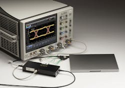
To do successful high-speed serial bus compliance testing, a test fixture is required. The test fixture provides an interface between DUTs and measurement/analysis equipment such as an oscilloscope (Figure 1). The fixture includes access to the transmitter or receiver measurement points required for compliance testing, and it enables product developers to verify the compliance of systems and components to the PHY test specification. Test fixtures are a critical element when performing quality compliance testing because their characteristics, such as reliability and repeatability, often compromise the specification margins for passing the electrical signal quality tests.
USB 3.1 Type-C testing
The new Type-C connection can carry USB 3.1 Gen 2 signals, transmit DisplayPort signals at up to 4k resolution, and handle up to 100 W of electrical power—all at the same time. USB Type-C is likely to become dominant among USB connectors. Also, USB Type-C ports can support a variety of protocols using “alternate modes,” which allows you to have adapters for HDMI, VGA, DisplayPort, or other types of connections from a single USB port.
The new USB 3.1 standard (enhanced SuperSpeed USB) defines a data transfer rate up to 10 Gb/s, which is twice as fast as USB 3.0 or 20 times faster than USB 2.0. The higher speed standard is driven by consumer demand and poses challenges in compliance testing.
Why does signal integrity matter?
As data rates increase, test fixtures and cabling cause more signal loss. So, to maintain high measurement accuracy, de-embedding techniques are used in many high-speed compliance tests to remove text fixture/cabling effects from the measurements, helping you see the actual performance of the DUT. This de-embedding can be achieved by characterizing the fixture through the measurement of S-parameters. For even better signal representation, you can combine this technique with a test fixture that already is designed for low signal loss.
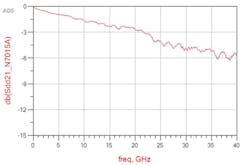
Insertion loss (Figure 2) is an important consideration when evaluating a test fixture’s quality. It gives the user a quantitative measure of the fixture’s performance. High insertion loss can compromise test margins and cause unwanted test failure.
Another consideration in achieving quality testing is cable loss. All cables have losses that will limit the performance of a test system. The amount of cable loss depends on the quality of the cable and its loss specifications. So, you want to pick a cable with lower signal loss and shorter length. The longer the length of a cable, the more the signal is lost.
De-embedding fixture effects
When performing compliance testing, the test signals from the DUT must pass through devices such as cables or test fixtures before being measured. Therefore, you end up measuring a combination of the DUT signal and the effects added from the test fixture and cables used to access the DUT. Ideally, you could isolate the DUT and only measure its performance. De-embedding software such as Keysight’s InfiniiSim lets you extract the DUT’s signal from the measured signal (Figure 3).
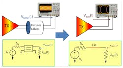
In this example, the eye diagram pattern of the PRBS signal is measured by de-embedding the cable and fixture effects. To perform de-embedding, the S-parameters of each cable pair and the fixture are measured and pre-installed in the InfiniiSim software. InfiniiSim analyzes the measurement and simulation circuits and generates a correction transfer function that, when applied to the measured waveform (VMeas), produces the desired simulated waveform (VSim) on the oscilloscope’s display.
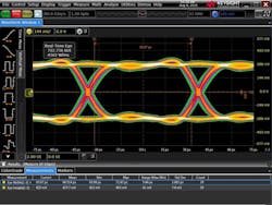
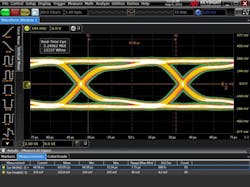
In Figure 4, a 13.5-Gb/s PRBS signal from a J-BERT was connected to a 33-GHz Keysight Infiniium oscilloscope (V-Series).
Figure 5 shows a signal measured through Keysight’s USB Type-C fixture, which is inserted between the signal source (BERT) and the oscilloscope. Note that there is noticeable rise/fall time degradation and the eye is more closed.
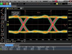
Figure 6 shows a measurement using Keysight’s InfiniiSim de-embedding function, which corrects for the loss of the test fixture and coax cable (1 meter long). The signal is almost perfectly restored by de-embedding the fixture effect.
Conclusion
Compliance test fixtures are critical tools when doing quality compliance testing. However, test-fixture characteristics, such as insertion loss, often compromise the specification margins for passing electrical signal quality tests. In many high-speed compliance tests, de-embedding techniques can be used to remove the effects of a test fixture or cable from the measurements to obtain the actual performance of the DUT.
About the author
Jae-yong Chang is the product manager and planner for Keysight’s oscilloscope product line in the Oscilloscope and Protocol Division based in Colorado Springs, CO. He joined Hewlett-Packard Korea in 1990 as a R&D design engineer and has held various positions in R&D and marketing in HP, Agilent Technologies, and Keysight Technologies. He received a B.A. and an M.S. degree in physics from Sogang University, Seoul, Korea.
About the Author
Jae-yong Chang
Product Manager and Planner, Oscilloscope and Protocol Division
Jae-yong Chang is the product manager and planner for Keysight’s oscilloscope product line in the Oscilloscope and Protocol Division based in Colorado Springs, Colo. He joined Hewlett-Packard Korea in 1990 as an R&D design engineer, and has held various positions in R&D and marketing in HP, Agilent Technologies, and Keysight Technologies. He received his BA and MS degrees in physics from Sogang University, Seoul, Korea.
Comment About the Article
To join the conversation, and become an exclusive member of Electronic Design, create an account today!

Leaders relevant to this article: