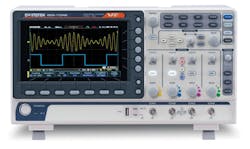
Today’s mid-range oscilloscopes include noteworthy innovations while predictably continuing the higher-wider-longer evolution. Gradual feature-set expansion in a general-purpose test instrument is to be expected. In a 2006 EE-Evaluation Engineering article about DMMs, Tee Sheffer, at the time president of Signametrics, said, “We see few applications that use more than 30% of the functionality of our DMMs. However, each application uses a different 30% than the previous one. You have to have a broad range of capabilities to address a major fraction of the applications even if no one application uses all the capabilities.”1
He easily could have been talking about scopes, which have taken advantage of semiconductor technology to provide new or improved functionality. All scopes acquire and process data but vary considerably in the details of what they do and how they do it.
Acquisition comprises the number of channels, signal conditioning, triggering, resolution, bandwidth, sample rate, and memory length. Processing includes data display, analysis functions such as the FFT and mathematically derived waveforms, mask testing, and communications capabilities. As datasheets grow longer with enhancements to each of these areas, prospective customers must decide which of the feature sets are affordable and best match both their current and probable future requirements.
Resolution
Bandwidth and sampling-rate increases have become commonplace, although in the past these generally were accompanied by 8-bit resolution. Various kinds of averaging and filtering can produce higher resolution from 8-bit data, but it’s only been within the last few years that natively higher-resolution scopes have begun to proliferate.
Achieving higher resolution together with high bandwidth is particularly challenging because of the associated noise. A note on the Teledyne LeCroy website states, “As with all members of Teledyne LeCroy’s HDO family, the [10-bit] HDO9000 utilizes an exceptionally low-noise system architecture that delivers outstanding effective number of bits (ENOB).”
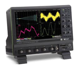
Teledyne LeCroy’s Robert Mart, product manager, further explained, “Our recently launched HDO9000 oscilloscope offers features that lend themselves to certain applications, such as power integrity or power supply characterization, EMC and EMI measurements, and radar testing. The instrument’s combination of 10 bits of vertical resolution, 4-GHz bandwidth, and a 40-GS/s sampling rate is in the sweet spot for these kinds of measurements” [Figure 1].
Courtesy of Teledyne LeCroy
He continued, “Similarly, when it comes to high-speed power analysis on GaN or SiC devices, the added resolution of the HDO9000 compared with 8-bit oscilloscopes provides greater precision and accuracy. This, in turn, results in a better characterization than with an 8-bit system. It’s also important to have enough bandwidth and sample rate to characterize fast switching edges and for the high-frequency-content signal to be analyzed with the higher resolution. The bottom line is higher accuracy in characterization of these high-speed devices.”
The Infiniium S-Series oscilloscopes from Keysight Technologies specifically address applications that require good signal integrity. These scopes also feature 10-bit resolution, a low-noise front end, and a 40-GSa/s sample rate. Keysight and Rigol Technologies have adopted “Sa” for samples to avoid using “S,” the abbreviation for Siemens (conductance) in the MKS units system. Only a few other manufacturers have followed suit. To emphasize signal fidelity and reduced noise, the datasheets for S-Series scopes and Teledyne LeCroy’s HDO9000 include representative ENOB values as well as a listing of RMS noise levels for each attenuator setting.
Keysight’s Robert Lashlee, marketing manager-digital product lines, explained that improved signal integrity was important, “… because it enables the engineer or technician to see on their scope the actual performance of their DUT. In many applications, having this high degree of signal integrity is vital because of the sensitivity required by the measurement.”
National Instruments recently launched the PXIe-5164 two-channel oscilloscope with 14-bit resolution and a 100-V pk-pk input capability. It’s true that 100 V is higher than the maximum range offered on many other modular scopes. Compared to bench scopes that may have a 10-V/div or 20-V/div range, it’s not that remarkable. Note that although NI calls the instrument a scope, rather than quoting V/div, the input ranges are specified in V pk-pk as traditionally is done for digitizers.
What makes the 100-V range important is its CAT II rating. You may be familiar with CAT I, II, and III ratings on DMMs, but not on scopes. The various safety category levels relate to how physically close a signal is to the “origin of installation”—the utility-level power input to a facility or any outdoor cable run (CAT IV). The category number decreases as you go farther from that point—CAT II is defined as receptacle outlet circuits and plug-in loads.
The reason for the distinctions among ratings is the greater probability of a large transient occurring the closer you are to the origin of installation. And, it’s transient protection that the category rating provides—806 V for CAT II. So, the real story behind the PXIe-5164 is the flexibility afforded to industrial system integrators who need to digitize waveforms while also providing the same safety and resilience as a CAT-II rated DMM. Having a 400-MHz bandwidth and a 1-GS/s sampling rate broadens the range of addressable applications.
Although launched a couple of years ago, the Pico Technology PicoScope 5000 remains unique. As described by Trevor Smith, business development manager, “The PicoScope 5000 Series scopes achieve flexible resolution by means of a unique architecture in which multiple high-resolution ADCs are employed at the input channels in different time-interleaved and parallel combinations to optimize either the sampling rate or the resolution.
“In time-interleaved mode,” he continued, “the ADCs are interleaved to provide 1 GS/s at 8 bits resolution. Interleaving reduces the performance of the ADCs, but the result, 60-dB spurious-free dynamic range (SFDR), is much better than oscilloscopes that interleave 8-bit ADCs. This mode also can provide 500 MS/s at 12 bits resolution. In parallel mode, multiple ADCs are sampled in phase on each channel to increase the resolution to 14 bits at 125 MS/s per channel and >70 dB SFDR. If only two channels are required, then resolution can be increased to 15 bits, and in single-channel mode, all the ADCs are combined to give a 16-bit mode at 62.5 MS/s.”
Smith concluded, “… [The process of] sampling in parallel with multiple ADCs and combining the outputs reduces noise and also both the integral and differential nonlinearity, providing outstanding single-shot dynamic performance.”
Accuracy
Many new instruments have significantly improved accuracy for the most sensitive attenuator ranges even though the DC and low-frequency specifications are marginally worse than for higher voltage ranges. However, these small differences are relatively unimportant compared with the much larger errors that can occur because of reduced bandwidth on sensitive ranges—an often-overlooked feature of older scopes.
Keysight’s Lashlee said that the S-series scopes featured full bandwidth at 2-mV/div sensitivity for full-screen signals. Similarly, Rigol’s DS2000A-Series scopes with bandwidths to 300 MHz and 2-GSa/s sampling rate (single channel) have full bandwidth on all attenuator settings including 2-mV/div, 1-mV/div, and an uncommon 0.5-mV/div range.
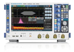
Siglent’s 200-MHz bandwidth SDS1000X/SDS1000X+ Series also offers full bandwidth on a 0.5-mV/div range, but DC gain accuracy reduces from 3% to 4% for settings ≤2 mV/div. Rohde & Schwarz features full bandwidth down to 1-mV/div in the RTO2000 although the guaranteed DC accuracy degrades slightly from 1.5% to 2% for ranges ≤5 mV/div. (Figure 2)
Courtesy of Rohde & Schwarz
In the past, a scope’s accuracy specification typically applied from DC up to 50 kHz. Today, more scopes also are specifying how flat the passband remains at higher frequencies—for example, the R&S RTO2000 brochure includes a graph of a measured amplitude vs. frequency response, and the datasheet quotes ENOB >7.0 for a full-scale sine wave up to the -3-dB frequency. Siglent specifies the SDS1000X/SDS1000X+ Series flatness relative to percent of bandwidth: ±2 dB for 10% to 50% of bandwidth, and +2 dB/-3 dB for 50% to 100% of bandwidth. Both amplitude- and frequency-related distortions affect the ENOB value, so listing high-frequency ENOB in the datasheet is a good indicator of otherwise unspecified performance.
Probes
Accuracy also is affected by probe performance, and recently there has been an unusually high amount of new probe activity. Keysight’s Lashlee described power integrity measurements as an example of an application that required “… a probe with low noise, low loading, high bandwidth, and support of popular rail voltages…. In the past, engineers tried to get away with using what was available in the market (probes or 50-Ω coaxial connection), but they missed a lot of signal detail.”
Keysight’s N7020A is a 1:1 active probe optimized for low noise, signal offset, and high bandwidth. To allow a DC-coupled signal to be shifted to the center of the screen where it can be viewed on a high-sensitivity range, up to a 24-V offset is available. The 50-kΩ input impedance reduces circuit loading, and the 2-GHz bandwidth handles fast edges and transients, allowing power-rail ripple and noise to be examined in detail.
So-called transmission-line probes are available from several companies. They provide an extremely low input capacitance because they use a 50-Ω coaxial cable terminated by the scope’s 50-Ω input. Looking into the open end of the cable, the impedance is almost a perfect 50-Ω resistance with virtually zero capacitance. Adding a 450-Ω or 950-Ω resistor in series results in a 10:1 or 20:1 probe, respectively.
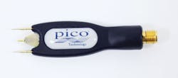
Yokogawa Test & Measurement’s Model 701974 PBL5000 5-GHz Low Capacitance Probe comes with both resistor values so you can interchange them as required. Pico Technology has developed the PicoConnect 900 Series probes (Figure 3) for applications up to 9 GHz. As described by the company’s Smith, “The probes employ a unique (patent applied for) in-PCB construction to create extremely low capacitance, coplanar microwave integrity, robust reliability, and low cost. This approach delivers a miniature fingertip-sized high-performance passive probe.”
Courtesy of Pico Technology
The problem with these probes and similar products from other vendors is resistive loading. Unlike a typical 10:1 high-impedance scope probe with a 10-pf input capacitance, a transmission-line probe’s much smaller capacitance doesn’t begin to degrade input impedance until very high frequencies are reached. The 500-Ω or 1,000-Ω input resistance is simply too great a load for many sources. On the other hand, the fidelity and cost of a transmission-line probe can’t be beat when probing low-impedance sources.
NI has developed probes for the automated test market in which many of the company’s products find use. As described by Ben Robinson, product marketing manager-modular instruments, the CP500X and CP400X coaxial cable probes, “… provide 10:1 attenuation at bandwidths of 500 MHz and 400 MHz, respectively. The adjustable compensation network at the input allows test engineers to tune the signal transmission lines within their fixed-connectivity test systems just as an engineer using a probe to manually test circuits would while also lowering capacitive loading compared to standard BNC and SMA cables. For example, a 1.2-m length of RG58 cable has a capacitive loading of approximately 112 pF while the 1.2 m CP500x has capacitive loading of approximately 10 pF.”
Also with specific types of applications in mind, Tektronix has developed the DC to 1-GHz TIVM Series of probes with IsoVu technology that facilitates high-resolution differential, floating measurements. As described by the company’s Varun Merchant, technical marketing manager, “[IsoVu] utilizes an electro-optic sensor to convert the input signal to optical modulation and galvanically isolates the device-under-test. IsoVu does not derate over bandwidth, offers … 106:1 common-mode rejection ratio (CMRR) up to 100 MHz, and provides complete optical isolation.”
He explained that common-mode interference can affect the accuracy of voltage measurements across floating current-sense resistors or on high-side gate drives in push-pull output stages. Because of its CMRR characteristics, IsoVu provides much better signal integrity for such measurements, which are required in power conversion and control applications. In another case, because the optical cable linking the probe tip to the controller can be as long as 10 m, a significant separation is possible between EMC instrumentation and the UUT, which minimizes interference from the UUT while maintaining electrical isolation without loss of bandwidth. Differential input impedance ranges from 50 Ω for a 1:1 sensor tip cable to 2.5 kΩ for a 50:1 cable.
At the 2016 IEEE Energy Conversion Congress and Expo, Teledyne LeCroy previewed a broadly similar high-voltage fiber-optic probe. This probe has a bandwidth of 60 MHz, CMRR >100 dB, and 10-MΩ input impedance. The company’s Mart commented that except for applications using the very fastest GaN devices, most users aren’t working with gate drive signals with faster than 10-ns rise time.
Other recently released Teledyne LeCroy probes include the HVD3206 2-kV and HVD3605 7-kV DC + peak AC differential probes, both with safety ratings per IEC/EN 61010-031:2015. The new CP030A (50 MHz) and CP031A (100 MHz) current probes have increased sensitivity compared to the earlier generation devices: 1 mA/div vs. the previous 10 mA/div.
R&S also has been developing new probes, including the RT-ZP1X, a 1:1 low-noise probe with 1-MΩ input impedance. The probe’s 39-pF capacitance is additional to the scope’s input C, and bandwidth is >38 MHz. Because the probe is used with a scope’s 1-MΩ inputs, AC-coupling to remove a power rail’s large DC offset is practical.
Memory length
A long memory allows a higher sampling rate to be used to acquire data for a given amount of time. For most vendors, the data acquisition memory length has become very large: R&S RTO2000—2 Gsamples total, Rigol DS4000—140 Mpoints max, Teledyne LeCroy HDO9000 Series—128 Msamples, PicoScope 5000 Series—512 Msamples max., GWInstek GDS-1000B—10 Mpoints/channel, Siglent SDS1000X/SDS1000X+ Series—14 Mpoints, and Keysight Infiniium S-Series—200 Mpoints/channel max.
Acquiring data at a 1-MS/s rate for a period of 1 second limits the nonaliased bandwidth to less than 500 kHz—preferably 200 kHz to have at least five samples per cycle. Increasing the sampling rate to 1 GS/s allows frequencies up to 200 MHz to be captured. Alternatively, 1,000x greater detail is available for 200-kHz signals. Of course, to acquire data for the same 1-second period, 1,000x longer memory is needed at a 1-GS/s sample rate.
As attractive as a long memory can be for certain applications, it is incompatible with a fast update rate. Specifications for several scopes quote update rates in the 106/s range, which means that each acquisition must be completed within 1 µs—assuming that triggers also occur that fast. Even a 10-GS/s sampling rate will only capture 10,000 points in 1 µs.
Also, note that the waveform update rate is not the same as the screen update rate, which typically is much slower. So, successive relatively short acquisitions must be merged in some way before updating the display. To achieve an extremely high waveform update rate, Tektronix developed InstaVu at least 20 years ago and has continued to refine the technology under different names such as FastAcq and DPX. As waveforms are acquired, the data points are entered into an 8-bit x display-width pixel map. For waveforms that are similar, certain pixels will be common. These pixels will have the highest value color in the resulting color-graded display. Other vendors provide similar types of display.
Some scopes feature a history mode that concatenates successive acquisitions one after another, filling the available memory. Each acquisition still is limited by the relationship between sampling rate and update rate, but you can scroll through the series of acquisitions to see how they vary and investigate the cause of significant changes. If it’s important to capture each trigger event, you may need to reduce the memory length or increase the sampling rate so that a trigger is not missed.
A long memory can eliminate the need to develop a highly restrictive trigger condition. Instead, it’s feasible to capture a large amount of data that includes events of interest and then search for them post-acquisition. Some vendors provide software tools to help with this. Most scopes support a zoom capability that allows you to manually review acquired data.
A further consequence of long memories is the need for data compression before display. As the DSO name implies, data is sampled and digitized in one of these instruments. In the horizontal direction, the display resolution is limited to the number of physical pixels, which means that several actual data points must be represented by each pixel. For very long memories, one pixel can be zoomed to reveal several thousand data points. Typically, a max-min algorithm is used to retain the highest and/or lowest value in the group of data points being compressed.
A long memory also facilitates more detailed signal analysis, although it also can highlight a scope’s computational weaknesses. The level of performance achieved in GW Instek’s GDS-1000B scope (Figure 4) addresses the problem. According to the company’s Roger Lee, product manager, some competing long-memory scopes down-sample acquired data so that the amount that must be processed is more manageable. While compression is necessary for display, it easily can lead to incorrect automatic measurement results.
Courtesy of GW Instek
Lee cited the integrated FPGA/CPU architecture of the Xilinx ZYNQ 7000 SoC used in the GDS-1000B as facilitating fast data processing. Specifically, down-sampling isn’t necessary because the processing performance is sufficiently high that the scope can “… achieve the maximum calculation within users’ acceptable time frame.” Further, he said, “The design team made good use of the high-speed data-transmission capability of the AMBA interconnect bus to allow the CPU to access acquisition memory with a data transmission rate of 1.3-GB/s per channel. Software engineers also made good use of the CPU’s NEON DSP engine to optimize the FFT algorithm, which completes megapoint FFT computing in 1.2 s…. The utilization of the floating-point unit avoids the effects of rounding and saturation in fixed-point implementations of the FFT calculation.”
Multiple instruments
A continuing trend is the integration of functionality in one box that previously required a few separate instruments. For many years, vendors have offered additional channels that can capture and display the activity on 16 or more digital inputs, mimicking a logic analyzer. Most companies have adopted the mixed-signal oscilloscope (MSO) terminology originally coined by Hewlett-Packard. Similarly, serial bus triggering and analysis have become accepted capabilities in all but the lowest cost scopes.
The Tektronix MDO4000C takes integration a few steps further. This is the latest version of the mixed-domain oscilloscope (MDO), which originally added an optional spectrum analyzer to a scope. The company’s Merchant explained that the MDO4000C also “… has an arbitrary function generator, a logic analyzer, a protocol analyzer, and a digital voltmeter. In addition, each instrument option is fully upgradable any time after purchase.”
The benefits of the original closely coupled spectrum analyzer and scope are evident in the MDO4000C. Merchant said, “The dedicated RF hardware acquisition system provides better RF performance and measurement flexibility than a typical scope FFT. The synchronized view of analog, digital, and spectral signals provides comprehensive cross-domain analysis, and the wide capture bandwidth (up to 3 GHz) offers unique single capture of an entire spectrum. Key spectral parameters such as center frequency, span, reference level, and resolution bandwidth are all adjusted quickly and easily using the dedicated front-panel menus and keypad.”
NI has upgraded the VB-8012 VirtualBench combination instrument that comprises an MSO, a function generator, a digital multimeter, a programmable DC power supply, and digital I/O. The MSO has gone from a 100-MHz bandwidth, two-channel, 500-MS/s (1-GS/s single channel) instrument to one with four channels, 350-MHz bandwidth, and a 1.5-GS/s per channel sampling rate. Ethernet connectivity also was added to the existing USB and Wi-Fi capabilities.
Summary
Even mid-range scopes have become very complex. Similarly, your design and test challenges no doubt have been getting more complicated over time as well as faster. Your applications require a number of channels, an amount of bandwidth, and a minimum amount of memory, resolution, and data processing. This group of specifications is the starting point to which other secondary capabilities can be added.
Tek’s Merchant said the company had found that “… close to two-thirds of oscilloscope users use spectrum analyzers as well…. The [MDO4000C] … addresses various testing challenges in areas such as embedded design and debug, power supply design and integration, EMI troubleshooting, and wireless integration.”
NI makes similar claims for the VirtualBench. The company’s website states, “By combining the most essential instruments into one device and integrating with PCs and iPads, the VirtualBench all-in-one instrument is simple and convenient and results in more efficient circuit design, debugging, and validation.” Of course, beyond the hardware, the VirtualBench is PC-based, which means that you can remotely view test results wherever it’s most convenient.
You can expect additional development of this type of product as well as further performance increases in midrange scopes. Which improvements will have the most impact? GW Instek’s Lee summed up the situation; “Different users have different requirements…. It is very difficult to point out which functionality is the most important one since we believe that any function facilitating users to identify problems should be defined as the most important function….”
Reference
- Lecklider, T., “Full-Function DMMs Streamline Test Systems,” EE-Evaluation Engineering, February 2006, pp. 16-22.
For more information
About the Author

