Finding cracked parts before they break


Courtesy of Rohmann Eddy Current Systems
Eddy current testing has been used for at least 50 years to inspect conductive parts for surface imperfections such as cracks or scratches. Fundamentally, the technique is comparative—it only determines anomalies relative to a reference. Because of this, fixturing may be needed to ensure that a curved part, for example, is always in the same position relative to a test coil or probe.
When alternating current is applied to a coil of wire, magnetic flux B is generated in the axial direction through the center of the coil. If the coil (probe) is brought close to a metal surface with the B field perpendicular to it, eddy currents will be induced in the metal. As these currents circulate in the metal, they generate their own opposing B field, which affects both the coil’s resistance and inductance.
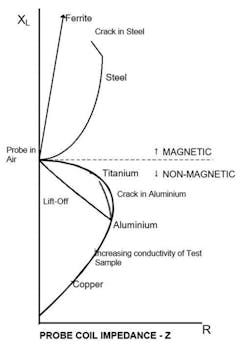
In Figure 1, the impedance plane display shows the effects of different types of material and also cracks. Because eddy currents mostly flow on the surface of the metal test piece, a crack will disturb the magnetic field lines and show up as a change in the probe’s apparent resistance and inductance. The direction in which the probe is moved relative to the crack and the sizes of the probe and crack also affect the display.
Source: Reference 1
Although finding cracks is a primary use of the technique, a large number of factors can alter a probe’s impedance. These include a change in material thickness caused by corrosion or simply by variations in the production process and material hardness because it affects conductivity.
Surface defect testing
The Olympus OmniScan MX ECA/ECT is a compact and lightweight instrument with Li-ion batteries providing up to six hours of inspection time. Details are easily seen on the 8.4-inch color display under any light conditions.
The base unit accepts one of two interchangeable modules and, in addition to eddy current testing, supports ultrasound scanning. The ECT4 module handles conventional eddy current testing as well as ultrasound C-Scan bond testing. Module ECA4-32 adds the capability to use an eddy current array with up to 32 channels or 64 with an external multiplexer.
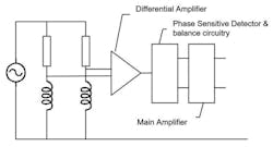
As the datasheet states, “Eddy current array (ECA) technology incorporates several traditional bridge (Figure 2a) or reflection (Figure 2b) … coils in order to achieve a much larger coverage in a single inspection pass. Additionally, each ECA probe model is carefully designed to maintain a high probability of detection of a targeted defect range, all along the probe length.”
Source: Reference 1
Source: Reference 1
An Olympus eddy current probe application note2 further comments on Figures 2a and 2b: “Older coils were normally connected to the two branches of a bridge configuration. Later coils have also been used in the reflection mode where separate coils are used for generating and detecting the eddy currents. Bridge coils give generally good performance, particularly if the probe is designed for a specific application and frequency. Reflection coils will often give a greater gain and a wider frequency range of operation but they are more complicated to manufacture.”
Zetec’s MIZ-200A eddy current array instrument features the surface array flex probe with 128 independent channels. As the datasheet states, “An array of eddy current coils utilizing proprietary X-probe technology provides [2-inch] wide inspection coverage in a single pass and can detect both longitudinal and transverse defects.”
The array probe is sufficiently flexible that it can wrap around weld beads up to 0.197-inch high while addressing smooth weld inspection including crown, toe, and heat-affected areas. And, according to the datasheet, the durability of the array pad was proven by testing more than 8,000 ft of stainless steel smooth weld surface without failure.
Corrosion can be detected under paint without stripping, and for crack detection, no surface preparation is necessary. The array detects longitudinal, transverse, and off-axis cracks as short as 0.02 inch and subsurface defects as deep as 0.039 inch. An optional encoder is available for accurate sizing and positioning of defects.
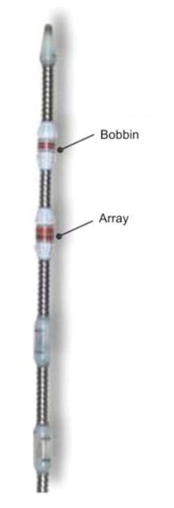
The model MIZ-200T performs test similar to those available on the “A” model but specifically handles tube testing in applications such as heat exchangers. Figure 3 shows part of the company’s X-Probe assembly with both bobbin and array elements as well as several plastic spacers that keep the probe centered in a tube. The probe is drawn through a tube to check for circumferential cracks, pitting, denting, wear, and thinning. Probes are available in a range of diameters to fit standard tubes and in 50-ft, 83-ft, and 110-ft lengths.
Courtesy of ZETEC
In general, ferromagnetic tubes cannot be tested using eddy current techniques because the material’s high permeability varies a lot and also minimizes penetration depth. However, steel and magnetic stainless steel tubes can be tested in the presence of a high DC magnetic field that saturates the material. Permeability is defined as the slope of the BH curve, and when the material is saturated, the slope approaches zero and the relative permeability equals 1.
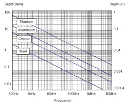
As shown in Figure 4, the depth at which defects can be detected depends on the type of material as well as the frequency at which the probe is operated. The range of frequencies is limited both by the probe characteristics and the capabilities of the test instrument. Nevertheless, lower frequencies penetrate more deeply but have less spatial resolution, and the opposite is true for higher frequencies.
Source: Reference 1
For good conductors, penetration depth, or skin depth, often is given by δ= .
where:
ρ = material conductivity
ω = angular frequency
µ = magnetic permeability
The 1.2-kg M3 Elotest instrument from Rohmann Eddy Current Systems is unusual in several ways beyond its very low weight. One aspect that a user immediately notices is the tester’s pictograph-based operation. In addition, communication in a choice of seven languages is available: English, German, French, Italian, Swedish, Chinese, and Spanish. Only one sub-menu level is needed for control. Coating thickness and specimen conductivity tests are supported as well as the usual crack and defect testing capabilities.
Two frequencies can be applied via a multiplexer running at up to a 1-kHz rate. Both frequencies are independently adjustable from 10 Hz to 12 MHz. Alternatively, the unit can automatically select the test frequency based on the probe characteristics. Single-coil probes are balanced using high-resolution internal compensation techniques.
An idea of the sensitivity needed to distinguish between good and bad parts is given by the 0.5-degree phase and 0.5-dB preamplification and gain step sizes available. Fine gradations of filtering also are selectable: low-pass from 1.3 Hz to 10 kHz in 40 steps; high-pass from 0 Hz to 10 kHz in 40 steps; and bandpass from 0 Hz to 10 kHz as a combination of low-pass and high-pass choices.
The company’s ARK 31-2 probe is a good example of how a particular application can be addressed by a specially designed probe. In this case, multilayered bolted connections needed to be inspected to ensure that there were no cracks between the bolt holes. As the datasheet states, “The ARK 31-2 is a toroidal core probe … designed for low-frequency tasks in the range from 30 Hz to 5 kHz. Its ring-shaped, focused eddy current field makes it less sensitive to interference from iron bolts or iron rivets. Its high penetration depth enables it to identify cracks in aluminum at depths of up to 10 mm.”
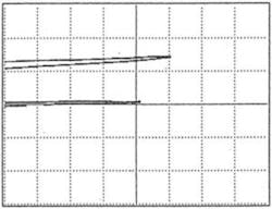
Figure 5a shows the probe in position and Figure 5b displays the impedance plane image corresponding to a crack at a depth of 6 mm between two bolt holes. The datasheet explains, “The signal in the middle of the image [5b] shows a nondefective connection while the signal above it is the crack…. A test piece with a defined defect is required in order to adjust the device parameter settings.”

Courtesy of Rohmann Eddy Current Systems
Courtesy of Rohmann Eddy Current Systems
Hardness testing
An eddy current testing paper3 considers the technique’s applicability to applications such as sorting fasteners according to their tensile strength or machine tool parts by their hardness. As the paper explains, eddy current testing can detect fine differences in microstructure nondestructively and very quickly. Figure 6a displays the large variation in permeability exhibited across a range of magnetic field strengths depending on material hardness and composition.
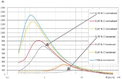
Courtesy of ibg
Clearly, testing at one magnetic field strength could distinguish between two or perhaps three types of materials, but determining which parts were good or bad is likely to be inconclusive. The company’s solution is to use multiple frequencies, which corresponds to testing at multiple magnetic field strengths. This principle is used in ibg’s eddyvisor S instrument that is optimized for testing “… material mix, heat treatment (hardness, case depth, temper), sinter density, and structure differences,” as described on the ibg website.
As shown in Figure 6b, even though the responses of the different materials are similar at field strength H4, one curve is quite distinct at H2 and another at H3. As Reference 3 recommends, “The frequency range from the lowest to the highest frequency should be at least 1:1,000 in order to vary, via the inductance of the sender winding, the exciting current and thus the field strength in the coil.”
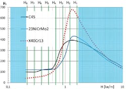
Courtesy of ibg
Another approach that has been developed is simultaneous harmonic analysis. According to a technical paper,4 “Harmonics are created through the hysteresis of the magnetization curve of a part inside a test coil. The sinusoidal current of the excitation coil results in an alternating magnetic field, which in turn, causes magnetic flux B in the test part. Depending on the permeability of the test part, the magnetic flux induces a distorted signal in the receiver coil. Fourier analysis of the distorted signal reveals harmonics of the 3rd, 5th, 7th, and 9th order. Analyses of these harmonics give an accurate picture of the magnetic properties of the test part, thereby providing detailed information of its metallurgical structure.”
Further considerations
If the probe is suitable for the application and the operator is trained to use the eddy current instrument, it should be possible to get repeatable good results. In addition to reliable inspection performance, GE’s Mentor EM tester emphasizes the benefits of wireless communications. As the company’s brochure explains, “With Bluetooth and Wi-Fi data transmission, collaboration can happen remotely—whether you’re on the tarmac inspecting landing gear, hanging off an offshore platform inspecting welds, or checking automotive bearings in a production line.”
UniWest has combined technologies in the EVi model eddy current tester to give operators both traditional impedance plane displays as well as a visual image. As the company’s website explains, “EVi provides a high precision, easily readable, visually accessible account of surface conditions, which enable greater operator accuracy, improved interpretation of data, and more accurate discernment of cracks, pits, gouges, and fretting.”
The Eddy Current Technology company specializes in simultaneous injection multifrequency test systems such as the Model ect 48 MICRO DOCK. Weighing only 5 lb, this instrument is a high-speed, fully featured four-frequency, eight-channel device suitable for inspecting any ferromagnetic or nonferromagnetic heat-exchanger tube. As the product’s datasheet explains, simultaneous injection mixes multiple frequencies so that the probe and test piece experience all of them at the same time rather than sequentially as would be the case if instead the frequencies were multiplexed. The advantages are speed—multiplexing four signals takes 4x as long—and precision. The responses to all the frequencies automatically are time aligned when the signal is digitized. Individual responses can be separated by filtering.
Because eddy current testing is a mature process, there is a wide choice of suitable instruments for most applications. Nevertheless, refinements continue to occur, and many manufacturers provide custom capabilities—especially probes—for challenging requirements.
References
- Buckley, J. M., An introduction to Eddy Current Testing theory and technology, White Paper, December 2001.
- Nelligan, T., and Calderwood, C., “Introduction to Eddy Current Testing,” Olympus, Tutorial, 1999.
- Baumgartner, H., Handbook of Induction Heating, Eddy Current Test, ibg, White Paper, 2014.
- Baumgartner, H., “Innovative Simultaneous Harmonic Analysis (iSHA) Eddy Current Testing,” ibg, Technical Note, October 2016.
For more information
About the Author

Tom Lecklider
Comment About the Article
To join the conversation, and become an exclusive member of Electronic Design, create an account today!

Leaders relevant to this article: