Testing EMI gaskets with Transfer Impedance and Shielding Effectiveness methods

Today’s electronic equipment must be designed to, first, operate in the electromagnetic (EM) environment it is to be employed in, and second, ensure that the EM fields generated by the system do not add significantly to the EM environment. These steps are accomplished by having the equipment housing simulate a “Faraday Cage” (that is, the electronic system functions properly without adding to the EM environment). The proper selection and use of an EMI gasket to seal the seams of an enclosure is the secret to obtaining a simulated Faraday Cage.
The ability of EMI gaskets to seal the seam of an equipment housing to create a simulated Faraday Cage is a function of the following variables:
- the conductivity of a gasket when applied to the joint surfaces to be used in actual application,
- the effect force of the gasket against the joint surface to be used has on the shielding provided by the gasket, and
- when required, the effects that moisture and salt fog environments have on the conductivity of the gasketed joints.
There are presently two methods employed by industry to test EMI gaskets. Those are Shielding Effectiveness (as contained in MIL-DTL-835281) and Transfer Impedance (per SAE ARP17052).
Transfer Impedance test methods have the ability to test all the variables of concern to an accuracy of ±2 dB over the frequency range of 10 kHz to 18 GHz and discriminate between the gaskets on the market over a range of more than 120 dB.
The Shielding Effectiveness test method, first, is known to provide highly inflated levels of shielding (a newspaper has produced over 100 dB of shielding at 2 GHz), second, does not test for the critical variables, third, provides the relative level of conductivity of a gasket over the dynamic range of 30 dB (versus 120 dB for transfer impedance), and fourth, cannot be used to predict a relative level of shielding at any given frequency.
Transfer Impedance testing
The Transfer Impedance testing used by industry is per SAE ARP1705 Rev C. The original ARP was prepared by the EMP engineering community to test EMI gaskets for compliance to the EMP requirements. The original document has been upgraded to include the needs of the EMC engineering community. These revisions have made it possible to:
- accurately measure the conductivity of a gasket to a level of ±2 dB over the frequency range of 10 kHz to 18 GHz,
- measure the conductivity of a gasket against any of the structural materials and finishes used by industry,
- measure the effects force of a gasket has when used against any of the structural material and finishes used by industry, and
- measure the effects moisture and salt fog environments have on the conductivity of a gasket when used against any of the structural materials and finishes used by industry.

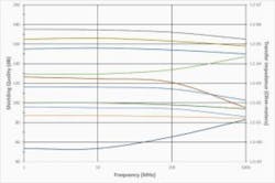
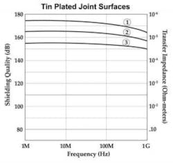
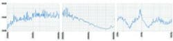
Figure 1 illustrates the Transfer Impedance test results of various EMI gaskets on the market. As illustrated, the ability to shield a seam in an enclosure by the various gaskets on the market varies by 120 dB. Figure 2 illustrates that the surface conductivity of a joint surface is a critical parameter. Figure 3 illustrates the importance of the force of a gasket against the joint surface of a seam has on the ability to seal the seam. (Traces 1, 2, and 3 represent, respectively, 30-lb., 10-lb., and 2-lb. forces on a Spira-Shield gasket.) And Figure 4 illustrates the loss of shielding a moisture soak has on the ability to seal a seam with an EMI gasket.
Shielding Effectiveness testing
Shielding Effectiveness testing as performed by industry is contained in MIL-DTL-83528 Rev. G. The original document (MIL-G-83528) was written by a manufacturer of the silver elastomeric gasket. The revisions to the document (which is controlled by a department of the DoD) is performed by members of the various manufacturers of the silver elastomeric gasket.
The test is a modified MIL-STD-285 (IEEE 199) test. The modifications are
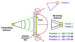
- the transmitting antenna is aimed at the center of a large (26-in. by 26-in.) 3/8-in.-thick aluminum plate instead of at the gasket under test, and
- the receiving antenna is aimed at the center of the large aluminum plate instead of recording the maximum field strength radiating from the gasketed area.
These modifications can produce inflated data of better than 60 dB.
The test joint surfaces are brass and aluminum. The force of the gasket against the joint surfaces is uncontrolled and can exceed 400 pounds per inch (where 1.0 pound/inch can be realized in actual use). The test data cannot be used to estimate the shielding at a given frequency. The test time is hours versus minutes for transfer impedance testing.
Figures 5 and 6 (which were obtained using the shielding effectiveness test contained in MIL-DTL-83528 Rev. G) reveal the following information:
Figure 5 contains shielding data of a newspaper tested at 2.0 GHz. As is illustrated, the shielding levels are 60, 75, and 93 dB, depending on
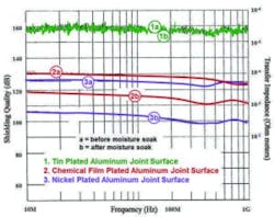
subjected to a 336-hour moisture soak
the location of the receiving antenna. Tests have been performed at several test facilities (including Chomerics) where levels greater than 100 dB were recorded. If the transmitting antenna were aimed at the newspaper joint, much different levels of shielding would have been recorded. The theoretical shielding of the newspaper (based on the capacitive reactance for a sheet of paper 0.001-in. thick) would have produced actual shielding levels of 24.6 dB. This reveals an inflated level of shielding of greater than 70 dB.
Figure 6 illustrates the shielding effectiveness test results of a (nonconductive) phenolic gasket 0.125-in. thick over the frequency range of 20
MHz to 10 GHz. As is illustrated, the shielding varies between 68 dB and 24 dB where the expected level of shielding approaches 0 dB over the frequency range. This renders some of the data inflated by more than 60 dB. This type of data illustrated in Figure 6 is expected to be obtained from all the gaskets tested to the standard. As is observed, such data is worthless to a design engineer in the selection of a gasket for a specific application.
Summary
Transfer Impedance test data provides a very accurate (±2-dB) level of the conductivity of an EMI gasket over the frequency range of 10 kHz to 18 GHz against any of the structural materials and finishes used by the electrical and electronic industry. This includes force of a gasket against the joint seam material. The ability to withstand moisture and salt fog environments can also be obtained when required. This conductive data can easily be converted to fairly accurate levels of shielding. In the event a selected gasket does not comply as required, a suitable gasket can readably be obtained.
Shielding Effectiveness data is highly inflated and erratic. Specific levels of shielding at a given frequency are not obtainable. A general “good, better, best” over a dynamic range of 30 dB is provided. However, this “good, better, best” can vary as a function of the structural material and finish a gasket is to be used against as well as the actual force to be applied. If the selected gasket fails to comply with a required specification, there is no guarantee a solution can be found using the test data.
Conclusion
The Shielding Effectiveness test method (used by major manufacturers of EMI gaskets to grade their products) produces highly flawed and erratic data. As such, the data cannot be used by the design engineering community in the selection of an EMI gasket for an actual application. Transfer Impedance test data provides all the information required.
It appears unlikely that the major manufacturers of EMI gaskets will supply their customers with Transfer Impedance test data on their products (unless they are forced to by their customers). However, if a company is interested in obtaining Transfer Impedance test data, it can be obtained at a fairly low cost. The equipment needed is a spectrum (or network) analyzer and the transfer-impedance test fixtures. The spectrum (or network) analyzer used to test for system EMC compliance should be available. The transfer-impedance test fixtures are relatively inexpensive, and a test will take 10 to 15 minutes to complete. EE
References
1. MIL-DTL-83528G, Detail Specification: Gasketing Material, Conductive, Shielding Gasket, Electronic, Elastomer, EMI/RFI, Jan. 23, 2017.
2. Coaxial Test Procedure to Measure the RF Shielding Characteristics of EMI Gasket Materials, ARP1705C, SAE International, Feb. 9, 2017.
About the author
George Kunkel is founder and CEO of Spira Manufacturing Corp. and has more than 50 years of experience as a design engineer. Since 1963, he has been active in both the SAE, where he has been involved in the preparation of various standards and has served as the chairman of a technical committee, and IEEE EMC Society, where he has presented more than 100 technical articles at various IEEE-sponsored international symposia.

Comment About the Article
To join the conversation, and become an exclusive member of Electronic Design, create an account today!

Leaders relevant to this article: