The ins and outs of relay AC performance testing
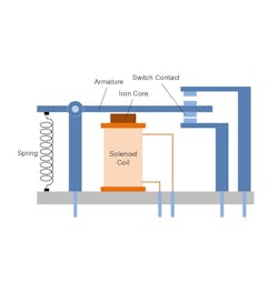
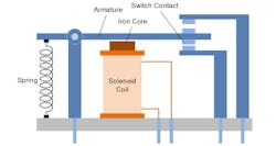
Relays are electromechanical devices that use a magnetic solenoid to actual a switch. When current is passed through the solenoid coil, it produces a magnetic field. The magnetic field is strengthened by the core, which is usually made of iron. The magnetic iron core attracts and pulls the iron armature lever down, and the lever is part of the switch. With the level pulled down, the switch is now making electrical contact and the switch is closed. When the relay’s solenoid current is off, the magnetic field is also off, and the spring pulls the armature up and the switch is opened. So, a relay is a switch that is actuated by electrical current.
Relays must be thoroughly tested during qualification stage, and there are a number of specifications that must be tested. Table 1 below shows some of the AC performance specifications. The coil actuation voltage may be from 3V to 28V or even higher, and the current required ranges from 10 mA to hundreds of mA, or more. To conduct relay performance testing, a high current transient driver is needed. A high voltage function generator amplifier with high output current and high output voltage is ideal for testing relays.
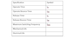
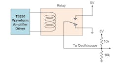
Figure 2 shows the AC relay test setup schematic and connection for testing relay AC specifications. As shown, the relay tester is consisted an amplifier driver, able to deliver both high voltage and high current to actuate the relay-under-test. Its terminals are biased with an arbitrary voltage of 5V, and its output is monitored by an oscilloscope. The two 10 k-Ohm resistors bias the contact to enable monitoring the transition time, as well as any bounce time (which we’ll discuss later).
Operate Time
Operate time—sometimes called make-time, pull-in time, or pick-up time—is the time it takes for the relay to close a switch from initially opened. Figure 3 defines the operate time, tO. At time T = 0, the electrical voltage is applied to the solenoid coil input. As shown in Figure 2, the coil is driven by a function generator amplifier with a square-wave or triangle wave. The high-voltage pulse needs to be long enough to allow the relay switch to close. When the switch is closed, the switch voltage transitions from low-to-high. The mechanical switch may be bounce around, resulting in high-low transitions. The operate-time is measured from the amplifier driver low-to-high transition to the switch output low-to-high transition. The operate-time spec does not include any bounce time.
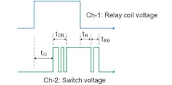
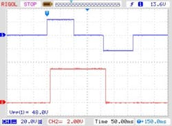
Figure 4 shows the oscilloscope capture of the operate time. The blue trace is the relay coil voltage driven by the amplifier, and the red trace is the relay normally-closed (NC) contact terminal voltage. About 3ms after the coil voltage transitions to 12V, the normally-closed terminal voltage transitions from 0V to 2.5V. This is because the armature is making a transition from NC to normally-open (NO) terminal. The 2.5V level represents the transition time duration that the armature is not in contact with either terminals. The transition time is approximately 150us.
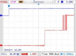
The first time the voltage reaches 5V is represented by the armature not making contact with the normally-open terminal. The time duration from the coil voltage rise transition (blue trace) to the first 5V rise transition is the operate time. The operate time for this relay is 4.5ms.
Relay Bounce Time
Figure 4—also captured by the oscilloscope—shows that the armature switch is bouncing for about 40us. This is the operate-bounce time, tOB. The relay bounce time is tested together with the operate-time. The operate-bounce time is the intermittent repeated low-high transitions immediately after the operate-time. That is, the operate-bounce time is the time measured from the first transition to the last transition.
Release-Time
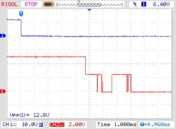
Similarly, the Release-Time, tR, (or Break-Time) is measured from the falling edge of the function generator amplifier output to the falling edge of the switch output. The falling edge of the waveform amplifier driver represents the removal of the current to the solenoid coil. Without the solenoid current and loss of the magnetic field, the switch is opened. The switch voltage will drop to zero, as shown in Figure 3 (tR). Again, there may bounce in the switch. The break-time does not include bounce time. As shown in Figure 5, the break-time when the red trace reaches 0V. The break-time for this device is 5.6ms.
Release-Bounce Time
The release-bounce time (tRB) is also tested with the release-time. The release-bounce time is the intermittent repeated high-low transitions that occur immediately after the release-time. That is, the relay bounce time is the time measured from the first transition to 0V to the last transition. Figure 5 shows the bounce time of ~2.5ms.
Maximum Switching Frequency
The maximum switching frequency (fMAX) is the maximum frequency at which the relay can make reliable switch transitions. To perform the maximum switching frequency test, the signal generator amplifier outputs square wave pulse train (50% duty cycle) to drive the coil. Use the same AC relay performance test setup as in Figure 2 to monitor the relay switch output making low-to-high and back transition. It is very important to use the two bias resistors. Then, increase the pulse train frequency until it is no longer able to switch. This is the maximum switching frequency.
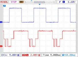
Figure 6 shows an example of relay switching at high frequency. For this relay at 50Hz, it still operates normally, but the bounce time is significant compared to the switch time. As the frequency further increased to 93Hz (not shown), the relay is no longer switching. At this frequency, it can no longer complete a switching cycle. Therefore, the maximum frequency is exceeded.
Because relays specified minimum, typical, and maximum coil voltage, the above relay performance testing must be retested over these voltage ranges, as well as temperature, if applicable. The electrical relay testing procedures are the same, but vary in the voltage and temperature, according the specifications.
Mechanical-Life
Mechanical-Life testing is similar to the operate-time and release-time tests above. To do this test, set the function generator power amplifier to output square-wave at 50% duty cycle and nominal frequency (i.e. 1Hz). Let the relay repeatedly energize and de-energize over time. At the same time, monitor the relay switching. Because the mechanical life is in the thousands and even millions of cycles, let the test run continuously 24 hours a day for days until the minimum number of cycles is met. For example, it completes 86,400 cycles in 24 hours at 1Hz.
Electrical-Life
Electrical-life testing is similar to Mechanical-Life testing, except the relay switch is loaded at specific conditions, usually maximum load current and maximum voltage. Repeat the same electrical relay testing procedures as mechanical-life until the specified number of cycles is met. Some manufactures provide data on Life-curve, which is a set of curves that shows the number operation cycle vs switch electrical current for one or more switch voltages.
Latched Relay Testing
So far, our discussion has centered mainly on single-coil non-latching relays. Another type of relay is the latched relay, which retains its last state even after power loss. There are two common coil latched configurations: single coil and two coils. The single coil latched type uses one coil, but uses positive current for set position and negative current for reset position. On the other hand, a two-coil latched type uses one coil for set and one coil for reset.
For the single coil latch relay, when the voltage and current is positive, the coil is set. For example, the switch is closed with positive current. When the current is negative (reverse direction), the relay is reset or the switch is opened. Testing single-coil relay’s AC performance parameters (shown in Table 1) requires both positive and negative voltages (positive and negative current). The ideal test equipment for testing the single-coil relay is an AC four-quadrant power supply driver such as the TS250 and using the same test setup as in Figure 2, but using both positive and negative voltages.
Figure 7 shows a test waveform example. The driving waveform first is positive voltage (+24V) to close the switch, and then the voltage may drop to zero (optional). While the voltage is at zero, it holds the relay position. Then the voltage is going negative to reset the relay and open the switch. Use the oscilloscope to monitor the switch output and measure the AC specifications in Table 1. Each spec is measured the same as non-latched relay discussed before.
For testing a maximum frequency using latched relay, use the waveform similar to Figure 6 above, except the voltage is switching from positive to negative with the zero-volt wait time eliminated. This is the maximum the relay can switch between the set and reset states.
For two-coil latched relay, AC timing testing may be a little bit more involved. The recommended test circuit is shown in Figure 8 below. This test configuration uses only one high-voltage function generator amplifier. When the amplifier outputs a positive voltage, the current flows through diode D1 to the set-coil and puts the relay in the set state (switch closed). Diode D2 blocks the current from going into the reset-coil. When the amplifier driver voltage drops to zero, the coil current will reduce to zero and the relay stays in the latched (set) state. Then, the amplifier voltage is transitioned to negative voltage. The current flows from the ground through the reset-coil and the diode D2 back to the amplifier output. The current now flows into the amplifier and is effectively negative current. Diode D1 blocks current from going into the set-coil. The relay is now in the reset state and switch is opened.
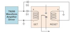
This test circuit with two diodes is effectively converting a two-coil latched relay into a single-coil latched relay. The AC performance specifications are tested using the same electrical relay test procedures as discussed before. The zero-volt holding time is optional as discussed before and can be omit when testing maximum frequency.
For dual-coil latch relays with common coil connection as shown in Figure 9, four diodes are needed. Similar to earlier, when the relay driver voltage is positive, the current flows through D2, the set coil, D2, andback to the driver. This will set the switch position. When the voltage is negative, the current flows through D4, the reset coil, D1, and back to the amplifier. This will cause the relay to reset.
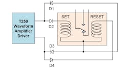
Typical diode voltage drop is ~0.7V (for silicon diode). So the driver voltage need to be set 0.7V higher to account for the voltage drop. Figure 13 configuration has 2 diode drops or ~1.4V. The relay coil voltage may be monitored using a differential probe, because their voltages are not ground referenced.
Conclusion
Relay AC performance and timing specifications and testing methods have been discussed here. The coil operation voltage can be 28V or more, and current can be as high as several hundred milliamps or more. Timing and performance specification testing require a high output voltage and high current amplifier for driving the relay coil.
About the Author
KC Yang
Product Marketing Engineer
KC Yang is a product marketing engineer at Accel Instruments, which specializes in high-frequency and high-current amplifiers for general lab bench testing. He received a Master of Science in electrical engineering from University of California, San Diego, and a Bachelor of Science in physics from Washington State University. He has published numerous application notes and article.
Comment About the Article
To join the conversation, and become an exclusive member of Electronic Design, create an account today!

Leaders relevant to this article: