The importance of integrated alarms in automotive device test
We depend on our cars to be reliable, comfortable, and most importantly, safe. Automotive technologies need to work under a wide spectrum of environmental conditions. This unique requirement extends the operating ranges of systems and electronics into areas far beyond consumer products. With the growing number of electronic subsystems in a car, the opportunity for malfunction is rising exponentially. This puts significant pressure on the reliability of automotive built-in electronics and drives strict semiconductor test
requirements.
When an entertainment or navigation system freezes, it is an annoyance, but imagine if a safety relevant system fails during an emergency. Advanced driver assistance systems (ADAS) such as blind spot detection, lane departure warning, pre-collision warnings, etc. are seen as the entry into more advanced systems, which will eventually lead to semi-autonomous and autonomous driving. Reliability is a key principle when human safety is depending on an electronic subsystem to function correctly.
Because of the critical risks associated with a failure in automotive systems, automotive device quality is much more demanding and challenging than other markets. Manufacturers and their suppliers play an important role in delivering dependable devices.
Automotive devices, unlike consumer or industrial devices, must be tested and function under extreme temperatures. The product lifecycle in the automotive industry is much longer, which adds the increased need for reliability. A drive toward failure rates of zero parts per million (ppm) is putting pressure on the manufacturing and testing of semiconductors for the automotive market. These fundamental differences in specifications require that the device test have inherent differences from consumer or industrial device test as well.
Semiconductor test is a key part of the manufacturing process of an integrated circuit. It validates that the device complies to its specifications and function. The main goal of testing is to screen out faulty devices (faulty with respect to its specification). Test intensity, which includes longer test lists and more test insertions at multiple temperatures, is increasing for automotive devices in order to verify every integrated block or function. A target of zero defects leaves no chance for gaps.
To improve the quality of shipped devices, there are additional efforts taken during device test to detect and screen out potential failing devices.
Methods to detect potential field failures in production
Special quality screening tests are performed during production test to identify devices that exhibit abnormal behavior which could indicate a potential failure in the field. Parts average testing is a common practice and is implemented by adjusting the test limits to a tighter set which represents the statistical performance of a test.
Stress testing is another important quality-related test. It mimics operating the device at or above the absolute maximum ratings and causes hidden defects to manifest in a device as a failure. High-voltage stress testing, combined with a leakage current test before and after the screening cycle, identifies latent failures.
In addition, it is important to avoid pre-damaging passing parts during test. In situations where a device under test (DUT) has been exposed to unplanned current or voltage levels, testing must be stopped and the part routed to the fail bin. Reliable voltage and current clamp circuits are needed in the instrumentation to avoid this. It is often preferred to stop testing immediately to avoid further damage and allow a root cause analysis of the failure.
It is crucial that an automotive device that has seen unplanned extreme test conditions will be reliably binned as a fail, even if it passes the entire test flow.
The importance of alarms to improve test quality
Alarms are a tester feature that trigger a notification if an instrument cannot satisfy its programmed condition. Whenever an instrument is unable to perform its programmed function, the tester software will force the device under test to fail as the default behavior.
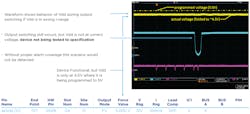
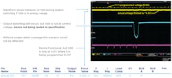
It is critically important to ensure that a programmed voltage or current is applied to the device, irrespective of device load conditions. Tests performed at maximum supply voltage would otherwise be useless if there was no guarantee that the Vddmax voltage level had been applied to the device (Figure 1).
It is also important to understand if there were some programming mistakes that may cause a test to pass unintendedly. This could be the case if an insufficient measurement range was chosen and the result was forced to be within the test limits. Alarms will flag this situation and prevent the part from passing.
Power instrumentation provides a specified energy to the DUT. It is critical that these instruments provide a mechanism to detect a condition in which the available energy of the instrument is depleted. Otherwise, this fault could remain undetected and the intended energy would not be applied.
A DUT may draw too much current in a test setup and the pulsed power energy storage could be depleted or the instrument may overheat. If this condition is detected, the test system can be programmed to avoid the condition or to adjust the test flow to give the instrument enough time to cool down or recharge to avoid instrument shutdown. If the instrument shuts down in order to protect itself from damage, testing has to be stopped for the device.
Another situation where alarms are required to quickly track a problem is broken Kelvin detection. If a force-sense Kelvin connection is weak or broken due to contact issues or problems on the device interface board (DIB), the VI instrument could run out of control due to an open feedback loop, resulting in unplanned current levels up to the clamps or voltage levels up to the supply rails of the instrument (e.g. a malfunctioning relay on the DIB). These situations are critical to be detected and the device must be binned out.
Instrument alarms detect conditions in which the programmed state is not met, and provide a mechanism to ensure that the test specification has been precisely applied. In addition, alarms assist in troubleshooting during test program development. Alarms may seem to be added effort, but in reality, they eliminate bugs and problems in the test program and accelerate reaching the goal of a correlating test program with better yield for production release.
Why integrated alarms make a difference
Integrated instrument alarms ensure that the correct stimulus is applied during testing without requiring the user to add extra hardware or software checks to the test application.
Alarms let the test engineer focus on the DUT and test list and not on any extra effort that otherwise would be needed to ensure the test setup. This leads to faster test times, less overhead circuitry on the DIB and therefore optimum throughput.
An alarm, as dedicated hardware integrated into the core of the instrument, ensures that faulty test conditions are detected in real-time. Alarm conditions are detected inside the control loop and are latched by the built-in alarm hardware. This provides a reliable mechanism to detect both persistent and transitional instances in which the programmed conditions are not met.
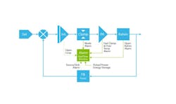
Figure 2 shows a block diagram of a DC instrument (VI). Slight variations in the diagram may exist, depending upon the instrument type.
Figure 3 shows a block diagram of a DC instrument (VI). Slight variations in the diagram may exist, depending upon the instrument type.
In general, the control loop of a VI instrument consists of a force value DAC (set) followed by a summing node (X) that compares the feedback signal (either current or voltage, depending on the programmed mode) to the actual sensed value. After the summing node, the difference of the set point and feedback (FB) is fed into the integrator stage (Int.), which is fed into the power amplifier (PA). The maximum current or voltage that can exit the power amplifier is limited by the clamp circuitry. Depending on the instrument, after the PA there could be a Kelvin detection element that identifies a broken force-sense loop.
The output signal (either V or I) is fed back to the control loop (FB) through the sense line (voltage forcing mode) or an internal voltage across a current sense circuit representing the forced current (in current forcing mode). Alarms can be triggered by various sources, as shown by the green box in the center.
As long as an alarm is latched by the monitor, the design guarantees that a deviation from the programmed condition will be reported automatically by the tester software polling the alarm registers.
With integrated alarms, the user does not need to manage the alarms, except masking specific alarms on desired pins as needed.
It is important that this alarm hardware is available in every VI channel. All instruments are monitored in real-time in the background. There is no user intervention required. When an alarm occurs on any instrument during a measurement, the alarm is noted in the data log for that test and the device can be routed to a specific alarm bin.
This allows for detection of a violation of the intended test setup on all channels that are connected during a test without additional effort (Figure 4). No extra resources are needed to confirm that the conditions are applied because the detection and validation capability is provided with the instrument.
An alarm on any connected instrument indicates the programmed state could not be performed and its forced value may not be within its specified accuracy. If this occurs, the test program routes that device under test to a dedicated alarm bin and forces a failure. A manual measurement-based alarm implementation will only guarantee up to the specs of the measurement instrument and does not provide real-time reporting.
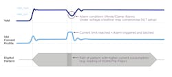
Without real-time alarms, the current or voltage would need to be digitized and evaluated for a violation during an entire test execution time. For example, given how long SCAN patterns can run, this may be impossible to verify by a measurement-driven alarm system as seen in Figure 5.
Alarms are a critical function of an automotive test system. They ensure that the correct test setup has been applied without any user intervention. For the strict requirements in the automotive market, alarms are an essential tool to achieve the required quality levels.
Alarms provide guidance to avoid or remove programming mistakes quickly, and contribute to a fast test program completion with the best quality.
In conclusion, with the increasing number of electronic subsystems in a car, the opportunity of a semiconductor device to fail is rising exponentially. The critical nature of automotive devices is driving strict semiconductor test conditions with increased test intensity to confirm every integrated block or function.
Integrated alarms play an important role by focusing on the test list of the DUT and avoid the need to implement additional instruments and tests that would be otherwise necessary to guarantee a critical stimulus. This not only leads to a faster test program development, but also due to avoiding additional tests, a better test time and higher throughput. EE
About the Author


