Cost-reduction and simplification: RDSon static parameter DC testing vs. pulse testing
Download this article in .PDF format.
The need for high-power semiconductors like diodes, MOSFETS, or IGBTs is increasing rapidly. All areas of renewable energy, e-mobility, or industrial electronic drives have a strongly growing need for more powerful components.
Testing these components is a big challenge for test engineers, since currents and voltages have been rising rapidly in the last few years and will continue as such going forward. To cut excess costs in mass volume production, these tests have to be done at different steps in the process, from front-end wafer level, bare-die, to back-end, where the discrete component and final product is tested. On one hand, this is mandatory to ensure consistently high quality and reliability of the devices. On the other hand, it is also important to detect failing parts as soon as possible—avoiding continuous processing of failed parts, and therefore lower production costs. The best cost-saving results can be achieved if you are able to completely cover test specification in every process step. For the most part, this isn’t easy. I’ll explain why—further along in this article—and provide an example that shows how you can work around problems by calculating for testing the RDS(on) static on-resistance parameter of a MOSFET. Most of that can be adapted to the measurement of Vf forward voltage of a diode or VCE,sat saturation voltage of an IGBT.
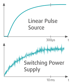
MOSFETs with RDS(on) drain-source resistance of less than 1m Ohm are already available onIn this article, we will discuss the advantages and disadvantages of measuring RDS(on) with direct current (DC)-based instruments, and current pulse sources in comparison. DC voltage and DC current sources have slow rise times that settle to a stable current level and need test times from 10ms or more. Thus, such tests are often performed within 100ms. Since 100ms is far away from any time constant of thermal elements in a typical test system setup (e.g. heating of contact pin/needle), we call that kind of testing “DC testing.” In comparison, we will show how fast current pulse sources can help to achieve test requirements.
The decision of which method of testing you choose for your test case has a dominant influence on all test system equipment. In one method it has to be DC-capable, and just pulse-capable with the other method. Simplified, a typical test setup for measuring the RDS(on) resistance consists of four different functional units, you should have an eye on:
- Current source
- Cabling
- High-current matrix/multiplexer
- DUT (fixture/needle adapter/wafer prober
The used current source itself is very different in design, depending on whether one is performing DC or pulsed testing. High-current DC sources are designed to supply energy continuously, and therefore also have a correlating cooling capability which both result in a larger form factor. Since they are based on switching power supplies, these provide output currents, which do have a certain ripple. It is important to take care of when performing measurements.
Beside the current source, it is the cabling, multiplexer, and the DUT adapter which will all generate—although they are stressed—ohmic and thermal losses when performing high-current tests.
Performing these tests with DC currents significantly increases the required effort for these system components. They have to be capable of handling 1.000A DC or more, and therefore the thermal power losses generated have to be cooled constantly. This results in devices like DC capable power sources, heavy and very low resistance cabling, big high current switching relays, and the need for many contacting needles. Every component has to be able to handle the system DC currents, so in consequence they are bigger, need a lot of rack and floor space, and are more cost-intensive for operating costs for all the years the DUT should be produced and tested.
The second way is smarter. By using very fast high current pulse sources, most components ofAs a rough estimate, one can say that initial system hardware cost of DC-capable test system and smart pulse test system may differ not very much. The big advantages of smart test systems are a much smaller space requirement and the ability to achieve a much higher system throughput due to the high test speed, which will additionally reduce cost for testing.
Ohmic resistance and parasitic inductance...
Since the size of these system components are mainly defined by their thermal capability, the Ohm’s Law is the major problem to fight. Thermal losses rise exponentially with rising currents: P = R * I * I (Ohm’s Law)
This means: raising the test current by a factor of 2 will raise ohmic power losses in relays, cable, and needles by a factor of 4. Raising the test current by a factor of 10 will then rise ohmic power losses by a factor of 100.
As if that wasn’t enough, forcing a certain current into a resistance-inductance-network (RL network)—what a series of cable, matrix and DUT represents—is taking linearly longer. That means 10 times the current takes 10 times the time: E = P * t
What does that mean for the relays, cables and needles? When bringing these two physical laws together, you can estimate that raising the test current from 500A to 1.000A by a factor of 2 will raise the thermal energy within the relays, needles, and cables roughly by a factor of 8. Raising the current by a factor of 3 rises the thermal energy by a factor of 27, and raising the current by a factor of 10 raises the energy by a factor of 1,000.
Another challenge on wafer- and bare-die-level is that the silicon itself may not be stressed thermally since there is no proper possibility for cooling the DUT in that production stage.
The thermal power losses in a MOSFET are likely the same as in any other ohmic resistor, so the same rules may be applied as we did before for cabling, matrix, and so on. But there is one major difference: The amount of thermal energy which could be brought into the DUT is fixedThe initial current rise time in an RL-network is defined by the overall inductance of the whole setup and the applied voltage of the current source. With that stated, the source is forcing the current into the system with 50V and the system has an overall inductance of 1µH, the current rises with di/dt = 50V / 1µH = 50A*10^6/s=50.000.000A/s=50.000/ms=50A/µs. Therefore, the current of 1.000A would be settled within 20µs. This would be the truth if not for the following facts:
- Current rise time of the source is limited
- Ohmic resistance is eating up the voltage
If the current rise time of your current source is the limiting fact, that could be solved easily. There are alternatives available on the market and the slow equipment can be replaced. The second problem needs a little bit more engineering and you need to take the total resistance of your test setup into account. Assuming a resistance of 40m Ohm for cabling, matrix, needles, and DUT in total, there is a rising ohmic voltage drop with rising currents, which ends up by 40V at 1.000A. This leads to the well-known curved e-function which is shown in the next figure. That e-function leads to a slower current settling. For a high speed 50V current source, that would result in a pulse duration of X µs until the current is sufficiently settled.
Nowadays the following inductance and resistance could be archived by some simple tricks:
- Current pulse source 50A/µs current slew rate
- Cabling <50nH per meter, 1mOhm per meter
- Matrix <250nH, 10mOhm
- DUT fixture: <100nH, 1mOhm
- DUT <5-50nH, 1mOhm
Christian Degenhart is CEO of VH Instruments GmbH. Since 2009 he has worked on the development of measurement instruments for fast production testing and is head of VX Instruments’ R&D since 2014. He can be contacted at [email protected].


