Protecting AI chips from thermal challenges during ATE test


An AI system has three components: large data sets, machine learning algorithms, and computing hardware to process the data. The demand for computing power specifically has led to a rapidly growing and highly competitive market for AI chips.
While AI chip designers are pushing die sizes toward the reticle limits of the silicon manufacturing processes, new innovative chip architectures are being introduced to maximize performance per square millimeter of die size. This has led to a rapid increase in device power density, which is quickly reaching the thermal limits of the silicon processes and device packaging technologies. It is projected that the amount of dark silicon, the part of a silicon die that must be powered-off to meet a given thermal design power (TDP) constraint, may reach 50% to 80% at 7nm. AI chip designers are investing a lot of time and resources in optimizing device heat dissipation and thermal management to minimize the amount of dark silicon on their devices.
Thermal challenges in ATE test
For these devices, the switching activities from structure scan test in device bring-up and in volume production further increase the device current draw which exacerbates the thermal issue in ATE test. It is likely that core supply current in AI chips will approach 900A (~700W) in 2019.
This is especially problematic in device evaluation and early production stages, where devices are not fully debugged, and test programs are in development. An unidentified device defect or an error in the test program could cause thermal runaway, a condition where device internal resistances would decrease, leading to higher currents and higher temperature. The situation leads to further lowering internal resistances until thermal damage occurs. This damages both devices under test (DUT) and the ATE’s Front End Hardware (FEH), including sockets, probes, and DIB interfaces. Thermal runaway results in both a financial loss as well as, and often more importantly, a delay in time-to-market.
ATE thermal protection requirements for high current AI chips
There are several key criteria that need to be considered for an ATE thermal protection system:
Real-time shutdown of power supplies. The response time of the protection solution needs to be much faster than other operations such as pattern bursts. It cannot rely on the operating system, which may be busy at the worst possible time doing testing related tasks. To ensure that sockets are not damaged during package test a 100ms response time may be adequate, but probe testing requires a faster response such as 50ms.
Entire site needs to shut down. The solution also needs to ensure that the power from multiple power supplies feeding a single site is shut down as well in case of an event.
Applicable to a wide range of AI chip designs. AI chips can have a variety of thermal sensors at multiple locations on a die, some accessible by analog measures and some accessible by register reads. Some chips do not include on-chip thermal sensors for time-to-market or other technical reasons. The ATE thermal protection solution needs to be able to work for all these scenarios.
No device yield impact. The protection mechanism cannot impact device test yields and ATE instrument performance or features. For example, if a shutdown mechanism fails all sites due to a thermal issue only from one of the sites, test yields would be affected.
Applicable to single-site and multi-site test: In addition to a shutdown of the core supplies, other supplies, instruments, and channels connected to that site should be shut down as well. Other sites, however, should not be affected. The failing site should be reset, appropriately binning the failed device and available to test the next device.
Key thermal protection elements in an ATE solution
There are two mechanisms that should be specified in an ATE solution to ensure proper response to any thermal issues involved in testing an AI device.
The over-current alarm system
The first level of protection rests in the current clamp architecture of the ATE system. To enable fast charging of the bulk capacitance, a dual-level clamping system allows for a higher than operating current to be applied without simply allowing full power which could damage FEH or degrade its performance over time.
The following chart shows a typical operation, where the DIB bypass caps are charged at the overload level limit, then the device draws an operating current that is less than the limit specified by the fold limit.
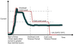
After this point, the ‘Fold’ limit timeout can be programmed from microseconds to seconds. If the current draw exceeds the limit for the programmed time, the appropriate alarm action will take effect (ignore, fail, bin).
The Interface Monitor shutdown mechanism
A good ATE system should feature a hardware real-time shutdown mechanism, or interface monitor. This will monitor the voltage drop between the supply and the DIB interface on a per-supply/per-site basis. If the voltage difference between the VS output point and the corresponding sense point is greater than the preset threshold value, an alarm for that site is triggered.
To illustrate how this real-time shutdown works, below is the process for the Teradyne UltraFLEX ATE with VSM power supply. To begin the test, a one-volt signal was applied on the UltraFLEX tester. A pattern was run that executes the following:
- Trigger the DC voltage input to start monitoring voltage at the VSM power supply output
- After 10ms, switch VSM-Force to the VS Alt voltage level (set to 1.1v)
- After 10ms, simulate the event
- After 10ms, switch back to the main voltage level
- After 10ms, gate off the VSM
The reason to switch to VS Alt was solely to provide a visible marker on the voltage trace. The red trace is with automatic shut-off trigger and the green trace is without this trigger.

This shows that the VSM output is shutdown within 500us after the trigger. (The slope change around 200mV is due to supply switching from driving 0V to connecting to the bleeder resistor.) Triggering Interface Monitor also triggered an alarm on the ATE software console. This meant:
- Alarm processing functions are automatically called
- Other supplies, instruments, and channels connected to that site would be shut down
- Alarm actions are executed, optionally failing or binning the site
- Site bin results are sent to the handler and the data log once all sites complete testing
Conclusion


Yi Zhang is a product manager in the Semi Test Division at Teradyne, where he manages the computing and communications product line. Zhang has been with Teradyne for four years, and his current focus is the artificial intelligence semiconductor market.
