DFT that gets AI chips to market faster
Download this article in .PDF format.
As the demand for processing power for artificial intelligence (AI) applications grows, semiconductor companies are racing to develop AI-specific silicon. The AI market is incredibly dynamic, with more than 50 startups and 25 established semiconductor companies all racing to capture portions of the emerging segment. This soaring growth in AI companies has created an environment of intense competition.
Success for these companies depends on getting to market quickly, and that means finding design and test solutions that address the challenges of the new AI chip architectures with the goals of achieving quality silicon with the fast time-to-market. We will focus here on the design of AI hardware, specifically, how to best test AI chips.
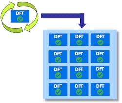
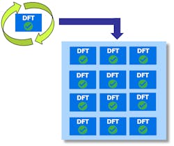
Both established semiconductor companies and a host of new startups are creating processors to handle the computer requirements specific to AI applications. Companies like Intel, Nvidia, and AMD continue to develop and optimize the existing architectures like GPU, CPU, and FPGA. AI processor startups like Graphcore and Mythic are creating ASICs based on the novel, massively parallel architectures that maximize the data processing capabilities for the AI workloads (Figure 1).
AI chips tend to be massive, complex, and designed at leading process technologies. While the architectures vary, they share a few key design characteristics, such as:
- Very large designs with billions of gates
- A very large number of replicated processing cores
- Distributed memories
The AI chip architectures and the critically important time-to-market requirements, influence the DFT implementation strategy. It follows that the traditional design-for-test (DFT) approach for full-chip flat ATPG breaks down when applied to AI chips.
We define three key strategies that work towards a time-to-market goal for AI chips:
- Exploit AI chip regularity
- Insert and verify DFT at the register-transfer level (RTL)
- Eliminate DFT-to-test iterations during silicon bring-up
Let’s take a brief look into each.
Exploit AI chip regularity
In the example shown in Figure 3, there are three levels of hierarchy: core (tile), block (supertile), and chip. The core (tile) is instantiated multiple times in the block (supertile) which is then instantiated multiple times at the chip level.
In a hierarchical DFT methodology, the DFT implementation, ATPG, and scan test pattern verification are performed at the core level. That is, sign-off is only performed once for any given block, then that signed-off block can be replicated to any number of instantiations at a higher level of the design. The same process is repeated at the block level for the interface logic and memory. Once the chip implementation is complete, the test patterns for core and block are automatically remapped to the top level by the DFT software. This process is much faster than performing all the DFT work and sign-off on the whole chip after all the physical design work is finished. Not only is it faster, but it also adds predictability to the project’s schedule because DFT is no longer in the critical path to tapeout. SoC design teams who adopt hierarchical DFT have seen up to 10x faster ATPG with 2x pattern reduction and radically accelerate bring-up, debug, and characterization of AI chips.
Hierarchical DFT also extends to post-silicon diagnosis and failure analysis. It allows for core-level diagnosis, which significantly accelerates the process.
Benefits of IJTAG
The benefits of hierarchical DFT are amplified when the chip also uses the IJTAG (IEEE 1687) standard for IP integration and test. IJTAG provides an amazing level of flexibility and automation for on-chip instruments. Any DFT software solution for AI chips should include IJTAG automation as part of the hierarchical DFT methodology. IJTAG enables two important aspects of hierarchical DFT: 1) hierarchical verification of the IJTAG infrastructure and 2) remapping core-level BIST and test setup IJTAG patterns to the top level.
For hierarchical verification, the IJTAG network inserted at the core level is verified first at that level then again with the IJTAG network of each higher level. When multiple instantiations of the core are replicated at the next higher level, the IJTAG network from the cores is integrated and verified automatically at that higher level. This hierarchical IJTAG network verification ensures that errors are discovered early in the design flow, avoiding any impact on the design schedule.
For IJTAG pattern remapping, the test setup patterns for scan testing such as scan-modes, low-power configuration, etc., and BIST patterns are generated and validated at the core level. The core-level IJTAG patterns are automatically remapped to the chip level, which is much faster than generating IJTAG patterns for the entire chip from the top level.
Hierarchical DFT with core grouping
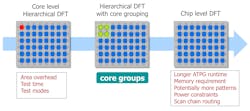
DFT implemented at the core level incurs an area-usage penalty because the DFT logic like isolation wrappers, compression logic, memory BIST controllers are duplicated in each core. However, if DFT is implemented at the chip level, it would result in longer ATPG runtime, large memory requirement to load the entire design, layout challenges when routing scan chains through all cores to the compression engine, and test power constraints as all scan chains are active at the same time.
AI chips need that “Goldilocks” implementation, depicted as the middle illustration in Figure 4, which groups multiple cores together for DFT. All the DFT logic is inserted and signed-off at the core group level. The DFT engineer decides how many cores to group based on the power, test pins, test time, and layout constraints of the design.
Other time-saving DFT techniques
Hierarchical DFT supports some key DFT techniques that help designers further cut DFT and test time, including:
- Broadcast the same test data to all the identical cores with channel broadcasting
- Share a single memory BIST controller between multiple memories in multiple cores
- Test more cores together without increasing the test power by using an embedded test compression (EDT) low-power controller
When an entire chip consists of identical copies of core groups, each core group requires the exact same test data. Channel broadcasting is a technique to broadcast the same test data to all the identical core groups. This helps reduce both the test time and test pin requirements. DFT software can help designers configure the number of input/output test channels to find the best results.
To reduce area overhead, a single memory BIST controller can be shared between multiple memories in multiple cores. A shared-bus implementation also allows for better implementation and connection of the bus to the memory BIST controller. In this flow, the DFT engineer does not need to alter any functional logic connected to the memories.
Regarding test power, the designer may want to add more cores to a group without increasing the test power. Adding an EDT (embedded deterministic test) low-power controller can enable better control of power usage during test.
Perform DFT insertion in RTL
DFT logic has traditionally been inserted at the gate-level design during or after synthesis. Using this approach for AI chips comes with two significant drawbacks.
- It takes about 4 times longer to simulate at gate-level than the RTL, and about 20 times longer for regression debug
- If working at the gate-level, any DFT logic or configuration changes require another synthesis iteration of the entire design before verification can be performed
A design may go through many iterations of DFT logic changes before it is finalized. For a huge AI chip, having to repeat simulation, debug, and synthesis for each iteration would significantly impact the design schedule.
Insertion of DFT logic in RTL—including IJTAG, memory BIST, boundary scan, EDT, logic BIST, and on-chip clock controller (OCC)—is faster because changes can be made without repeating synthesis. RTL-level DFT also allows for early I/O and floor planning of the chip, which shortens the whole physical design cycle.
In addition to DFT logic insertion, testability checks can also be done at the RTL level rather than waiting until ATPG to find coverage problems. Designers can achieve higher test quality in less time by performing DFT checking and fixing most testability issues at RTL before running ATPG.
Eliminate DFT-to-test iterations
Speaking of eliminating iterations, the silicon bring-up process can be radically streamlined. The traditional process of silicon bring-up typically involves the multiple iterations between the DFT domain and the test/ATE domain for pattern debug, characterization, test optimization, and test scheduling. The back-and-forth between the DFT engineer and the test engineer is particularly inefficient in the early stages of silicon bring-up when the dominant source of the issues is still unknown. However, DFT engineers can now perform the silicon-bring up themselves, and the test engineers can run diagnosis in several resolutions from flop-level to net-level without the help of DFT engineers using a desktop debug solution.
One of the leading AI chip companies, Graphcore, adopted this solution not only for silicon bring-up but also for complete testing of their parts. They were able to complete silicon bring-up within three days, and ship fully tested and validated parts within the first week, far ahead of schedule (according to results presented at the 2018 ITC symposium).
Conclusion
The semiconductor landscape is poised for the arrival of new ICs specific to the demands of AI applications. As companies race to get their chips to market, design teams are adopting DFT techniques that are better suited to the challenges of AI chips, including
- Exploiting AI chip regularity
- Performing DFT insertion in RTL
- Eliminating DFT-to-test iterations
Rahul Singhal is a Technical Marketing Engineer—Tessent Solutions, at Mentor, A Siemens Business. His focus is on the industry requirements in the areas of ATPG, compression, low pin count testing and DFT for AI chips architectures.


