How the VRT Packet Structure Accelerates Optical Communications
In October of 2017, the AXIe Consortium, the VITA trade organization, and six companies announced a new standard called the Optical Data Interface, or ODI for short. Based on optical links between instruments, instead of electrical links, ODI can stream data up to 20 GBytes/s from a single optical port, with speeds up to 80 GBytes/s through port aggegation. ODI is designed to address challenging applications in 5G communications, mil/aero systems, high-speed data acquisition, embedded systems, and communication research.
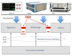
ODI links, being a separate pluggable interface, can be placed on any product regardless of form factor. Figure 1 shows a diagram of a sample recording and playback system that combines any combination of bench instrumentation, AXIe modular instrumentation, and PXI modular instrumentation.
ODI has created a specific profile of the VRT packet structure that allows VRT packets to be executed at FPGA hardware speeds. By standardizing on VRT, and defining a VRT profile that can be executed by FPGAs, ODI can deliver not only the high speeds due to the optical links, but also all the advantages of VRT, a signal-oriented packet standard. Some of those advantages include standard data formats, both real and complex, a multitude of timestamp options, packet alignment for port aggregation, and various events and error reporting.
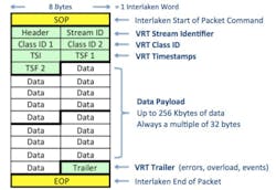
Figure 3 shows the structure of a VRT signal data packet. The packet is very flexible, and can be used with any signal type, any number of channels, and any resolution. With only 32 bytes of overhead per packet, and data payloads up to 256 Kbytes in length, VRT offers very high efficiency.
ODI packets are graphically presented as 8 byte words across, and sequential words going downward with time. Eight bytes matches the 64-bit Interlaken word that the physical layer protocol is based on. Interlaken is a chip-to-chip protocol defined by Cisco and Cortina Systems that is available from all major FPGA vendors. It can be used to transport any packet type. ODI uses Interlaken to transport VRT packets. A VRT packet is bounded by the Interlaken Start of Packet (SOP) and End of Packet (EOP) command words, shown in yellow.

Several features come with the adoption of VRT by the ODI standard. The Prologue and Trailer, denoted as green cells, bring new capabilities not available in standard measurement buses. Here is a brief list of the new capability, viewed by examining the packet structure header. The header denotes the type of packet being sent, and its length. VRT also allows Context Packets and Control Packets. Context and Control packets can occasionally send metadata about the signal, such as its RF and IF frequencies, bandwidth, and amplitude. ODI-2 defines how any packet in the complete taxonomy of VRT packets can be transported and executed.
The most common ODI application is the transmission of synchronous single–channel or multi-channel sample data from one device to another. This is called a stream. In most applications, a single stream is sufficient, as all data is synchronous. Streams can contain thousand of channels, if necessary, or just one.
These streams are each identified by a unique Stream ID (identification) number. Stream ID is retained when data is stored, so the entire sequence can be recreated when played back to an ODI-capable signal generator. Stream ID is also used during port aggregation to associate the ports together as one large data pipe. Finally, Stream ID identifies one stream from another, allowing multiple, asynchronous streams to be transported across the same ODI link.
Class ID (identification) plays a key role in interoperability, as it specifies the data formats to be used in the data payload. The ODI-2.1 Data Format standard uses an algorithmic approach so the Class ID unambiguously determines the number of signal channels, complex or real numbers, binary or floating point, the length (number of bits of resolution) of each data sample, and the packing method.
ODI-2.1 also allows for a method to include events on a sample by sample basis, when indicated by the Class ID. These may be trigger signals, markers, overload detection, or any of a number of different event definitions. Everything is included in the Class ID fields to completely determine the meaning of the data payload, even between vendors.
Timestamps are a very important aspect of ODI, and are without parallel in other measurement buses. ODI embraces the VRT timestamp capability, where the absolute time of the first sample is specified in the Integer Timestamp (TSI) and Fractional Timestamp (TSF) fields. Though timestamps are optional in ODI, they bring new synchronization capabilities between devices. ODI allows UTC, GPS, and free running sample counts as timestamps (Figure 4).
All ODI Signal Data VRT packets end with a trailer. This allows to identify events that occurred during the data stream, such as an overload or loss of AGC lock. The flexibility of the VRT data payload is a key reason ODI embraces VRT. As mentioned in the Class ID paragraph above, nearly any combination of signal channels, data formats, and packing methods may be used.
ODI-2.1 specifies the mandated and permissible formats. 8-bit and 16-bit data handling is required by all devices, but a device may use any resolution in-between. Real and complex data is supported, as well as channel counts from 1 to 8192. These resolutions match well with the speeds delivered by ODI. Longer data sample lengths and floating point representations are also allowed.
Embedded Applications
While ODI was conceived by players in the electronic test market, VRT was invented by VITA for embedded applications. This expands the possible applications for ODI beyond electronic test to include embedded applications such as those found in mil/aero avionics. ODI’s adoption of VRT allows new synergies.
First of all, embedded designers can use VRT over the ODI interface for very high speed data communication. VITA 66 defines standard optical ports, typically deployed on a VPX backplane. ODI is compatible with the VITA 66 definition, and could be deployed as the optical interface between VPX modules, carrying standard VRT packets. Additionally, the alignment of data packets and formats between measurement applications and embedded applications will lead to synergies in the design and development of embedded systems, as instruments and processing units can directly interface with the optical links of the embedded systems. This will enable critical measurement and processing functionality early in the development
process.
Conclusions
ODI is different from all other test and measurement buses. It is a high-speed pointto-point interface that carries real-time signal data. The speeds, data formats, and timestamps are optimized for wide bandwidth multi-channel data, as found in 5G, radar, electronic warfare, and other RF applications. Its data bandwidth exceeds that found in standard electrical interfaces, and it can be cabled up to 100 meters between devices.
Ports can be configured in parallel for more speed, and there is a roadmap to more per-port speed to come. It has standardized data formats that are both, general purpose and ideal for software defined radio applications. It changes the measurement system paradigm from connecting analog signals between instruments, to connecting digital signals between measurement devices, processors, and storage systems. It is as applicable to embedded systems as it is to measurement systems.
ODI is literally a ray of light to address challenging new measurement and embedded applications. The complete set of ODI specifications can be found on the AXIe website at http://axiestandard.org/odispecifications.html
About the Author
Comment About the Article
To join the conversation, and become an exclusive member of Electronic Design, create an account today!

Leaders relevant to this article: