How to Prepare for Battery-Cell Discharge Testing to Low Voltage
Members can download this article in PDF format.
What you'll learn:
- What type of equipment is best to use for low-voltage test of battery cells?
- What is an electronic load, and how does it work?
- How to overcome a major limitation with the low-voltage-discharge test.
When discharging battery cells, it’s sometimes desirable to discharge the cells to a low voltage. Under normal operation, care must be taken to prevent discharging the cell below the safe operating voltage of the cell. However, when testing cells, the purpose of the test may be to characterize cell behavior when pushed below normal operating voltages.
In this article, I will focus on lithium-ion cells whenever I use examples of voltage thresholds, but the challenges and solutions to low-voltage testing are the same—independent of the cell chemistry.
Referring to my example of a lithium-ion cell, the minimum discharge voltage is when the open-circuit voltage (OCV) of the cell hits the voltage associated with 0% state of charge (SoC). While the minimum OCV of each lithium-ion chemical formulation, such as iron phosphate or nickel manganese cobalt, is different, this number is typically in the 2.5-V range. Some chemistries can go down to 2 V or even lower.
Depending on the nature of the test, you may want to keep within the safe operating voltage or drive the cell down lower in voltage. For example, if you’re performing a cell cycle-life test, the goal is to properly cycle the cell between charged and discharged states. This determines how long the cell will survive before it loses its ability to adequately hold a charge.
For this test, you will want to keep the cell within its normal operating OCV range to prevent damaging the cell because of over-discharging or over-charging. By contrast, for safety testing, you may want to deliberately discharge the cell beyond its minimum OCV to characterize its behavior and determine when the cell becomes damaged or even dangerous.
Low-Voltage-Discharge Test Equipment Choices
To conduct these tests, you will need test equipment capable of discharging cells to a low voltage. In a cell characterization lab, such as found in an electric-vehicle OEM, you will be testing many cells and have many tests to perform, so dedicated turnkey cell test equipment is warranted.
For some users, such as the design team of a small IoT device, cell testing may be just a small part of their overall design task. For this lab, a dedicated turnkey cell tester may not be worthwhile. Instead, standard benchtop power supplies and electronic loads may be utilized for the occasional cell test. Table 1 describes various types of test equipment that can be used.
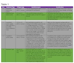
From Table 1, you can see that there are two cases for test equipment (Table 2).
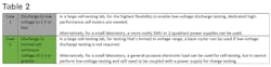
For case 2, what is the cause of this limitation on low-voltage operation? Why can the more expensive equipment for case 1 operate down to 0 V but not for case 2? The answer is related to how power electronics operate to produce negative current to discharge cells.
How Does an Electronic Load Work?
Fundamentally, an electronic load or a cell-discharge circuit in the battery test system must present a load on the cell to pull current out of the cell. In its simplest form, that load is a resistor. Due to Ohm’s Law, the current through the load resistor would be a function of the voltage across the resistor. So, as the cell discharges, the cell voltage would drop and the current through the resistor would drop, resulting in a non-constant current load condition.
Therefore, in practice, no cell test equipment company would propose to use a resistor, as they’re not programmable, and they cannot produce a constant current load on the cell.
Instead, in its simplest form, test equipment uses a transistor, typically a field-effect transistor (FET), to discharge the cell (Fig. 1). The FET looks like a resistor that can be varied by a control voltage. The current through the FET is measured using a current-sense resistor (i.e., a current shunt). The measured current is provided as a feedback signal to the discharge control circuit so that the current can be regulated to a fixed constant-current value.
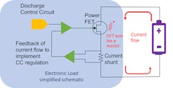
The discharge control circuit adjusts the resistance of the FET to maintain the required constant current out of the cell independent of the cell’s voltage, creating a variable resistor that’s controlled to draw regulated constant current from the cell during a test. The power being drawn from the cell is the product of the voltage of the cell times the current being drawn from the cell.
For some test systems that are either lower in power or less sophisticated, the power being drawn from the cell is dissipated as heat. In more sophisticated systems, the power is captured and regenerated back to the ac line.
Limitations and Solutions for Low-Voltage-Discharge Testing
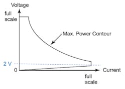
While this FET load method has worked quite well for years, it suffers from a limitation. As the discharge control circuit wants to draw more current, it programs the FET to have lower and lower resistance. Eventually, the FET’s resistance cannot be “turned down” any further—it has reached its minimum resistance, known as the full-on resistance of the FET.
Once the FET reaches this minimum resistance, it just operates as a fixed, very low resistance. As the voltage of the cell goes toward 0 V, the maximum current that can be drawn drops linearly because of Ohm’s Law:
Max_Available_Load_Current = Cell_Voltage / FET_Full-on_Resistance
This behavior is visible in the discharge characteristic of the cycler channel or electronic load (Fig. 2).
If you need to go below 2 V with a basic cycler or an electronic load, there’s a solution. It’s possible to put a boost supply in series with the output of the cell (Fig. 3). This boost supply adds the required voltage to keep the input voltage to the cycler or electronic load above this minimum operating voltage such that the discharge control circuit never has to push the FET to its full-on resistance state.
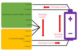
The boost supply can be complex to configure and adds extra cost to the test setup. But if you must test at low voltage and you’re limited to the equipment you have available, this may be a viable choice. In a future article, I will cover how to configure a boost supply to allow for low-voltage operation.
For case 1, where the test equipment can go to 0 V or even negative voltage, the boost supply is effectively built into the tester architecture. Therefore, the cell test channel or SMU can, by design, achieve low-voltage operation without the external boost supply, thanks to its internal boost supply. While this gives you the greatest flexibility, it does mean the testers are more complex and will carry a higher cost.
Summary
If low-voltage-discharge testing is required by your test protocol, it’s recommended to buy test equipment that supports low-voltage-discharge testing below 2 V. For cycle-life testing, where your test protocol never requires low-voltage-discharge testing, you can achieve a measurable savings by selecting equipment that doesn’t support operation below 2 V and doesn’t have a built-in boost supply.
About the Author

Bob Zollo
Solution Architect for Battery Testing, Electronic Industrial Solutions Group
Bob Zollo is solution architect for battery testing for energy and automotive solutions in the Electronic Industrial Solutions Group of Keysight Technologies. Bob has been with Keysight since 1984 and holds a degree in electrical engineering from Stevens Institute of Technology, Hoboken, N.J. He can be contacted at [email protected].
Comment About the Article
To join the conversation, and become an exclusive member of Electronic Design, create an account today!

Leaders relevant to this article: