Unraveling Measurement Accuracy Specifications for Battery Testers
Members can download this article in PDF format.
What you'll learn:
- Defining accuracy and error in the realm of test equipment.
- The four ways to specify accuracy.
- Interpreting actual error vs. specified error.
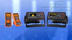
When specifying and purchasing cell and battery test equipment for your R&D lab or production line, it’s critical to understand its performance specifications. While it may be easy to clearly state price, how many channels you need, and current per channel, the accuracy of the equipment is perhaps the most important specification. However, it can be a challenge to understand and ensure you’re specifying your needs correctly.
Getting Started: What is Accuracy and Error?
When test equipment makers, like my company Keysight Technologies, refer to accuracy, we specify accuracy as the amount of error you will see with respect to the parameter. For instance, if we’re talking about current measurement accuracy, we specify the amount of error you will encounter when making a current measurement, such as 100 µA of error or uncertainty on a current measurement of 5 A.
If we’re talking about current programming or source error, it concerns the error in setting the desired current value. So, if you want to set a constant current charge rate of 10 A, the system may have a programming error of 25 mA. Thus, you will not actually achieve 10 A, but an output value within 25 mA of 10 A.
While the examples given were for current sourcing and measurement, this concept applies to any parameter that can be measured, such as voltage in volts, current in amps, resistance in ohms, temperature in degrees, pressure in various units, etc. Similarly, you will have a sourcing or programming error for any parameter that can be sourced by the system, which is normally limited to voltage and current.
This topic might seem to apply just to channels in a cell or battery tester or formation system. However, these accuracy specification concepts work with any measurement device (e.g., a voltmeter or internal resistance measurement instrument), or to any source device (e.g., a power supply, source-measure unit, or analog output signal generator).
Often, measurement resolution is mixed up in any discussion of measurement accuracy. I’ll cover resolution at the end of this article.
Ways to Specify Accuracy
In general, there are four ways to specify accuracy. The actual number established by the accuracy specification is the amount of error you will encounter. Based on this amount of error and the true value of the desired parameter, you can then determine the accuracy. For the remainder of this discussion, I will refer to measurement accuracy, but the concept applies identically to programming or source accuracy.
1. Fixed error
In this case, the error is a fixed value, such as 10 mA. It means that no matter how large or how small the parameter you’re trying to measure, there will be the same amount of error. For example, if the error is 2 mA, you will have 2 mA of error whether you are measuring 100 mA or 100A.
2. Fixed percent of range
Here, the error scales with the range of the measurement device and will be specified as “% of FS” (means percent of full scale) or “% of range.” For example, if the error is 0.2% of FS and the full-scale range is 10 A, then you will have 0.2% of 10 A, which is 0.02 A or 20 mA of error. On many measurement devices, you will see ranges. One benefit of the ranges is to match the range to the size of the parameter being measured to ensure the lowest error in measurement.
Let’s look an example. You’re trying to accurately measure a 500-mA signal. Your measurement device has three ranges: 1, 10, and 100. If the error is 0.2% of FS, the error will be 2 mA of error on the 1-A range, 20 mA of error on the 10-A range, and 200 mA of error on the 100-A range. While the 500-mA signal can be measured on any of those three ranges, you will get the lowest error when using the lowest range.
3a. Gain and fixed offset
In this case, there are two components to the error: A gain term that gives an error component that scales with the size of the parameter being measured, and a fixed term that’s always present. You will see this error stated as something like “% of reading + value.” Accuracy specified as a gain and fixed offset can apply to a measurement device with a single range or multiple ranges, because the specification doesn’t include “range” in the specification.
For example, once again, you’re trying to accurately measure a 500-mA signal. Your measurement device has an accuracy specification of 0.1% + 750 µA. The gain term is 0.1%, so the gain-term component of error will be 0.1% of 500 mA or 500 µA. The fixed-term component is 750 µA. Therefore, the total error when measuring 500 mA will be (500 µA + 750 µA) or 1.25 mA.
If the measured signal were to go up to 1 A, then the error would go up as well. At 1 A, the gain-term component of error will be 0.1% of 1 A or 1 mA. The fixed-term component would remain at 750 µA. The total error when measuring 1 A will be (1 mA + 750 µA) or 1.75 mA.
This is the best way to specify accuracy. While it’s more complex to calculate, it means the measurement device is well characterized by the test equipment provider. On top of that, it will give the lowest error for each value measurement made because the error scales with the size of measurement.
3b. Gain and offset as % of range
Fundamentally, this case is the same as case 3a, but the fixed term is calculated based on the range of the measurement. If there’s only one measurement range, then case 3a and 3b are identical.
To look at an example, you’re again trying to accurately measure a 500-mA signal on a system with a 5-A range. Your measurement device has an accuracy specification of 0.1% of reading + 0.1% of range. The gain term is 0.1%, so the gain-term component of error will be 0.1% of 500 mA or 500 µA. The fixed-term component is 0.1% of 5 A, or 0.005 A. Therefore, the total error will be (500 µA + 5 mA) or 5.5 mA.
Actual Error vs. Specified Error
While the cases above explain how to interpret and apply accuracy specifications, what’s critical to know is “what is my error on my measurement”? After you’ve calculated the error term, you will want to compare this error term to the measurement you’re making. Let’s revisit cases 2 and 3.
In case 2, you’re trying to accurately measure a 500-mA signal. The measurement device has three ranges: 1, 10, and 100 A. If the error is 0.2% of FS, the error will be 2 mA of error on the 1 A range, and you select the 1 A range to ensure the most accurate measurement.
If you compare this error term to the measurement you’re making, you have 2 mA of error on a 500-mA measurement. This is 2 mA/500 mA = 0.4% error in your measurement, even though the accuracy specification was 0.2% of FS. Clearly, you can’t just say my measurement will be 0.2% accurate because the specification was 0.2% FS.
In case 3, you’re once again trying to accurately measure a 500-mA signal. The measurement device has an accuracy specification of 0.1% of reading + 750 µA. The gain-term error component is 0.1% of reading, so this component of error will be 0.1% of 500 mA or 500 µA. The fixed-term error component is 750 µA. Therefore, the total error will be (500 µA + 750 µA) or 1.25 mA.
Comparing this error term to the measurement you’re making, there’s 1.25 mA of error on a 500-mA measurement. This is 1.25 mA/500 mA = 0.25% error in your measurement, even though the accuracy specification was 0.1% + 750 µA.
Also, important to note, is that error terms are applied as a ± to the measured value. If the error term is 2 mA on a 500-mA measurement and you want to know the range of results, you must both add and subtract the error term from the measurement as follows:
- Error term = ±2 mA
- Value to be measured = 500 mA
- Resultant measurement minimum = 500 mA – 2 mA = 498 mA
- Resultant measurement maximum = 500 mA + 2 mA = 502 mA
So, this is saying if the error is 2 mA on a 500-mA reading, the measurement device will return a measurement between 498 and 502 mA.
The table shows a comparison of how to calculate and apply these three cases.
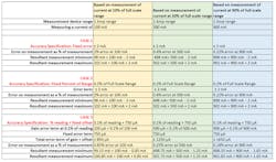
Note that the resultant error as a percent of the measurement reduces significantly as the measured values increase toward the maximum of the measurement range. With the fixed errors (cases 1 and 2), the resultant error as a percent of measurement suffers because the error is fixed, while with case 3, the resultant error scales with the reading, improving error as a percent of measurement at small measurement values.
Beware
There’s another method to specify accuracy—and beware if you encounter it. If you see accuracy specified as a percent only, like 0.2% accuracy, the specification is misleading. While it may be very easy to understand and calculate, it’s unrealistic.
Let’s look at an example. You’re trying to measure 500 mA with a measurement device specified at 0.2% accuracy. The error term of 0.2% of 500 mA is 1 mA of error. If instead you were trying to measure 1 A, the error would be 2 mA, as it simply scales. But what about the other direction?
If instead of measuring 500 mA, what if you wanted to measure 50 mA? Would the error be 100 µA? And what about measuring 5 mA? Would the error be 10 µA? If you were trying to measure an open circuit with current of 0 mA, does this mean the system will report 0 mA with 0 µA of error, indicating a perfect measurement?
It’s unrealistic that any measurement instrument could provide a constant error of 0.2% regardless of the size of the signal. When the accuracy is specified as a percent of reading, something is missing that describes the limitation of the measurement device at its low end. Therefore, you really can’t trust the performance of this measurement device, especially at the low end of its measurement range.
And Finally, What About Resolution?
Frequently, resolution is thought to be more important than accuracy, but this isn’t the case. While resolution can be a figure of merit that gives some indication of the quality and performance of a measurement device, as in 18 bits is better than 16 bits, the accuracy is the real governing specification on how good a measurement you can make.
For example, if your measurement device has a high resolution of 10 µA, and an accuracy of 50 µA, the 10 µA has no real bearing on the measurement as measurement error will be ±50 µA. The 10-µA resolution doesn’t impact or improve the accuracy of the measurement device nor will it give you any higher confidence in the measurement, which will never be better than ±50 µA.
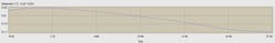
Having high resolution can be helpful to see the relative relationship between consecutive measurements, such as watching temperature drift, where you might see a 0.1°C change over time on a 25°C measurement that has ±2°C of accuracy. However, on an absolute basis, you can’t say, for instance, that the temperature is 25.7°C vs. 25.8°C with full certainty because the measurement accuracy of any individual reading is ±2°C (see figure).
Summary
Understanding the performance specifications of your cell or battery test system is critical. By discerning how to interpret and apply the accuracy specifications, you can be certain you will request the right capabilities without over-specifying or under-specifying your needs when requesting a quotation. Likewise, you will be sure to know what you’re buying and how well it fits your needs when reading a datasheet or a statement of work for a customized system.
About the Author

Bob Zollo
Solution Architect for Battery Testing, Electronic Industrial Solutions Group
Bob Zollo is solution architect for battery testing for energy and automotive solutions in the Electronic Industrial Solutions Group of Keysight Technologies. Bob has been with Keysight since 1984 and holds a degree in electrical engineering from Stevens Institute of Technology, Hoboken, N.J. He can be contacted at [email protected].
Comment About the Article
To join the conversation, and become an exclusive member of Electronic Design, create an account today!

Leaders relevant to this article: