Understanding Battery-Cell Test System Software
What you'll learn:
- Key elements that drive a battery-cell tester.
- Three main architectures used to construct a tester.
Battery-cell testers are commercially available at many different levels of performance. Performance parameters for voltage and current include slew rate, rise time, setpoint accuracy, measurement accuracy, update rate (how fast the setting can change from one setpoint to the next), and measurement speed (how fast the system can capture data, typically measured in milliseconds per measurement).
When selecting a test system, these performance parameters are often the main consideration when determining if the tester is right for your application. Of course, beyond these performance parameters, the tester must have the correct number of cell test channels and the right channel size (maximum voltage and maximum current) to test the battery cells that must be evaluated.
The testers on the market today not only have different levels of performance, but they offer different system architectures that can impact the smooth operation of your test lab. A system architecture refers to the overall scheme by which the tester software interacts with the tester hardware.
Heart of the Battery-Cell Tester
Power and measurement hardware, which lies at the heart of the tester, provides energy into and out of the cell while measuring its behavior. Figure 1 shows a simplified block diagram of the tester channel hardware. A power amplifier connected to the cell acts as a voltage source (during constant voltage charging and discharging) and as a current source (during constant current charging and discharging). In some systems, when discharging, the energy can be recovered.

The power amplifier is driven by a digital-to-analog programming stage, where digital programming instructions are converted to signals to be amplified to the right voltage and current to charge and discharge the cell. If waveforms, like a drive cycle pattern or pulsed discharging, are desired, then the digital programming system will need to update the programming to the amplifier at high speed. This requires some kind of waveform file to be downloaded to the channel from the tester software.
Along with power electronics for charging and discharging, the channel hardware has digitizing circuits to measure the voltage on the cell, which is typically a 4-wire measurement. The digitizer can also measure current, which is typically done with a current-sense resistor, sometimes called a current shunt. The performance of this resistor is critical for making precision current measurements.
The speed of the measurement system is dictated by several factors: Is the system making high-accuracy voltage or current measurement of steady-state values (like a DMM) or digitizing a rapidly changing signal (like a scope or digitizer)?
If trying to make individual, steady-state measurements that achieve maximum accuracy and noise rejection, a long integration time of 100 ms (for 50-Hz AC power systems) or 120 ms (for 60-Hz AC power systems) is used, but this limits how fast the voltage or current can be digitized. If trying to digitize a signal, a digitization speed of 100 measurements per second or 1,000 measurements per second may be used. When digitizing the data, the resultant block of measurement data will need to be captured, locally stored, and later uploaded to the tester software.
System Architectures for Cell Testers
Innovative engineers have developed many architectures to construct cell testers, but in general, three system architectures are used to build them:
- Software control direct to cell channel hardware
- Software UI to embedded computer to cell channel hardware
- Software UI to internal hardware sequencer to cell channel hardware
For the remainder of this article, I will refer to the computer that’s running software as the control PC. In fact, it could be a Linux computer, or a proprietary system, or even something running in the cloud. But for simplicity, let’s call it the control PC.
Software control direct to cell channel hardware
In this architecture, the control PC acts as the user interface for writing programs, launching programs, running the program, collecting data and viewing data. The PC is connected to the cell channel hardware over an interface like Ethernet, USB, or some proprietary interface (Fig. 2).
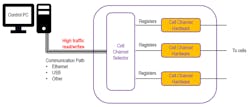
The cell channel hardware is directly controlled step by step from the control PC. Often, this is done by sending instructions to registers in the channel hardware to update programming values and reading registers to return measurements.
Since every action on the channel hardware requires some read/write activity from the control PC, there’s a high amount of traffic on the communication interface. The speed of these systems is limited by the speed of the communication interface. If using Ethernet, activity from other operations on the LAN can disrupt the tester’s operation.
Because the tester requires fast and continuous read/write activity, any disruption of the data stream has harmful effects to system operation of the system and, thus, isn’t a robust setup. Systems based on this architecture tend to cost less because of the simplicity the components needed: just a PC connected to a set of register-based cell channel hardware.
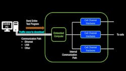
Software UI to embedded computer to cell channel hardware
In this architecture, the control PC acts as the user interface for writing programs, launching programs, collecting data and viewing data. However, the PC isn’t responsible for continuously controlling the channel hardware. Instead, this job is given to an embedded computer in the tester.
The embedded computer talks over a dedicated communications interface to the cell channel hardware. Because this interface is dedicated, the speed of the read/write traffic on the interface is tightly controlled and managed. The test is launched by the control PC and the embedded computer then executes the program. Data is collected by the embedded computer, and test data and results are returned to the control PC.
This system can operate more quickly because the data flowing between the control PC and the tester is minimal while the test is running. Instead, the high-bandwidth operation is between the embedded computer and the cell channel hardware. Systems based on this architecture tend to be more expensive due to the cost of the embedded computer and its operating system plus support electronics.
This architecture has two variants: step-by-step and full program download.
With step-by-step download (Fig. 3a), each step of the test program is downloaded from the control PC to the embedded computer to reduce complexity of execution on the embedded computer. However, this means that the test program can’t execute and move on to the next test step without the control PC. Therefore, other control PC operations, like LAN communications or UI activity, may cause disruption in communication between the control PC and the embedded computer, which negatively impacts system operation.
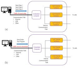
With full program download (Fig. 3b), the entire test program is downloaded to the embedded computer, which does all of the work. While the embedded computer has a more complex job, the benefit of this scheme is that the entire program is executing on the embedded computer. As a result, the control PC can be separated and even disconnected from the embedded computer. This system is also more robust, as other control PC operations, like LAN communications or UI activity, don’t impact the executing test.
Software UI to internal hardware sequencer to cell channel hardware
This architecture is similar to the previously described full program download scheme—the control PC software acts as the user interface for writing programs, launching programs, collecting data, and viewing data. And again, the control PC isn’t responsible for continuously controlling the channel hardware.
Instead, that job is given to an embedded sequencing engine in the tester (Fig. 4). The embedded sequencing engine is a sophisticated CPU or microcontroller directly driving the cell channel hardware, achieving speed and timing found inside any digital system design.
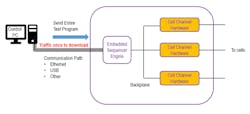
The benefit of this scheme is that the control PC can be separated and even disconnected from the tester because the embedded sequencing engine is doing all of the work. When the test is launched, the control PC sends the whole test program to the embedded sequencing engine, which then executes the program. Data is collected by the embedded engine, and test data and results are returned to the control PC.
This system can operate more quickly because it’s not required to have data flowing between the control PC and the tester while the test is running. Instead, the complex embedded sequencing engine is running the tester standalone.
The system is extremely robust, as other control PC operations, like LAN communications or UI activity, don’t impact the executing test. Systems based on this architecture tend to be more expensive than PC-direct-to-hardware systems because of the added expense of the embedded sequencing engine, but less expensive than using an embedded computer. Due to the complexity of the design and implementation of these embedded sequencing engines, though, not many test vendors offer this architecture.
Summary
While performance parameters like measurement speed, setpoint accuracy, and channel current capacity are the main considerations when selecting a battery cell tester, you should be mindful of the system architecture. Every system can be simplistically viewed as PC running software controlling a stack of cell channel hardware. But there are pros and cons to each architectural design that can impact the speed, robustness, and price of the cell tester.
About the Author

Bob Zollo
Solution Architect for Battery Testing, Electronic Industrial Solutions Group
Bob Zollo is solution architect for battery testing for energy and automotive solutions in the Electronic Industrial Solutions Group of Keysight Technologies. Bob has been with Keysight since 1984 and holds a degree in electrical engineering from Stevens Institute of Technology, Hoboken, N.J. He can be contacted at [email protected].
Comment About the Article
To join the conversation, and become an exclusive member of Electronic Design, create an account today!

Leaders relevant to this article: