What's All This Teflon Stuff, Anyhow?
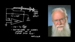
Once upon a time, a long time ago, a friend of mine, Arnie Liberman, designed a really good operational amplifier with a very low bias current - less than 0.1 pA. Now, when you want to measure and test a current as small as that, you don't just measure the I x R drop across a resistor, because even with a 100,000-MOhm resistor, it's hard to get resolution or accuracy. (0.1 picoamperes x 100 kMOhm = just 10 mV). So Arnie set up a test with an integrator. If this amplifier had an output drift rate (or ramp rate) of 5 mV/s with a feedback capacitor of 10 pF, that would prove that the amplifier's input current was 5 milli x 10 pico, or 50 femtoamperes.
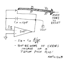
But you can't just run an integrator without resetting it occasionally. And Arnie knew you could not easily find a relay that would short out the feedback capacitor without introducing lots of leakage and a bad jump when you turned off the drive to the relay's coil. So he made up a "relay" by applying a lever to a long push-rod which reached into the sealed box where the test was going on. The push-rod would close the contacts and short out the capacitor. Then when you backed off on the push-rod, the integrator would integrate the current, and all you have to do is measure the output's dV/dt to tell if the input current was within spec. And this worked fine, even at the level of small femtoamperes.
It worked fine in 1971 ... it worked okay in 1972 ... it worked in 1973. But after you started the test, you had to wait many seconds for the output dV/dt to stabilize to the point where you could get the right answer. Later, in 1973, you had to wait almost a minute to get the right answer.
In 1974, when you had to wait 3 or 4 minutes to get any valid reading, somebody in Production Test finally complained to Arnie that you couldn't get very many units tested in a day. So Arnie went to trouble-shoot the test fixture. And he was puzzled for a while. What could cause such an erroneous reading? Soon, he realized that the push-rod was the culprit. If you pushed it back and forth, just a tiny bit, the integrator went berserk. But how could that be? The push-rod was made of Teflon. And it slid in Teflon bushings. How could there be a big error caused by the push-rod?
But as it turned out, that was indeed exactly the problem. When the push-rod slid in its bushing, it generated thousands and thousands of volts of static electricity. Now, on most ordinary insulators, those charges would drain off shortly. But because Teflon is such a good insulator, the charges would bleed off over a long, long time (through the air). Some of this charge would go into the summing point of the amplifier - for many seconds.
As the Teflon got drier with time, the time constant got longer and longer until he had to fix it. Arnie replaced the Teflon push-rod and Teflon bushing with a grounded metal push-rod, in a grounded bushing, with just a tiny sliver of Teflon insulator on the end that pushed against the switch contacts. The problem was banished. It just goes to show that if you have the best materials, and the finest concept, and you misapply things just a little, you can get some terrible results.
Recently, I was testing some of my operational amplifiers, LPC662's, with MOSFET inputs. The bias current was consistently down in the 2- or 3-fA area. It was so small that it really was hard to measure. I had a 10-pF integrator running, similar to Arnie's, but I was trying to get 20 times greater resolution. The resolution was marginal, as there were some jumps in the signal. The signal had long tails and additional errors if you tested a good amplifier after a bad one had pegged. And the switches didn't always give zero error on a damp day. So I wrote down a list of the fixes I needed, and I set my new technician Paul to work on them.
Paul made some imaginative and bold improvements. I had suggested that he should plot the ramp on a strip-chart recorder. Paul set up a digitizing scope and programmed it to spit out the answer scaled directly in femtoamperes.
I asked Paul to set up a simple circuit to drive a 6-V reed relay so there wouldn't be much charge coupled into the circuit from the voltage that drives the coil. Paul set up a clever adaptive circuit to take advantage of the small difference between the relay's pull-in and drop-out current, so that he fed the coil 2.6 V all of the time. You only had to hit the coil with a small pulse of voltage, positive or negative, to close or open the contacts, respectively.
I cautioned him that if the wires wiggle, they can couple a lot of charge and noise into the input. Paul strung the whole circuit up on rubber bands, as a shock mount, so that people walking on the floor nearby would not ruin the measurement.
Also, I cautioned him that we would soon need a good, low-leakage socket, guarded with Teflon insulation. Again, Paul gave me better than I asked for, with a big slab of Teflon for all of the components to be mounted on or above.
I explained to Paul that the slow recovery from overload was caused by the silver-mica feedback capacitor which had poor dielectric absorption. I gave him a capacitor that I had made - filled with air - about 0.5-in.-by-2 in.-by-4-in. of air, to make a 5-pF capacitor. It had copper plates and guarded copper side-frames.
Now, first of all, why am I telling you all of these details? If I design a tester with greatly improved performance to help me test a really high-performance product, why should I tell all our competitors so that anybody in the world can test their products using the improved tester? Why should I give away all of these hard-earned secrets?
Here's a preliminary answer: It's probably true that some competitors might learn how to test better and faster if I give them my techniques. But my customers will also learn faster. There are more of them, and it's more important to teach them, because they're still trying to come up the learning curve. There's not much point in keeping secrets about testing if our customers are kept in the dark. It's just not fair to make your customers guess what is a good way to test your products.
Note that that is not the same as telling the customer exactly how we test it (we have testers, big expensive Teradyne setups, with monstrous interface boxes and complex software, and it would be much too complicated to tell everybody exactly how we run each test). But we do feel obligated to give any customer a good, valid test circuit that gives the same data as our production tests.
Okay. Paul set up this fixture. But there were a few little problems. For one, the output ramp would occasionally give a jump at random times. This jumping seemed worse than previously. Also, I asked Paul to test a whole group of parts, and he said, well, it would take longer than one day to test those parts.
OH?? I knew Paul could test those parts in less than a day - unless there was something wrong. I asked, well, why can't you test a part in a minute or two? He replied, "The output is off-scale and doesn't even come on-scale for 2 minutes." That didn't seem right. It wasn't until 3 days later that I slapped myself on the forehead at 6 a.m. - it was the Teflon factor. Paul had added lots of Teflon around the circuit, and the charge stored on its surface was the major cause of the long tails. When I got to work, I asked Paul to cover up as much of the Teflon as he could with aluminum foil - and ground it. He said the settling got a lot better. So he then removed all of the Teflon, and the slow settling went away. Just like Arnie's problem and Arnie's solution, 16 years earlier!
The next problem was with those darn' jumps. Now, we could program the tester, not just to test the ramp for 60 seconds, but to test for six 10-second segments. If the answer was the same for 3 or 4 of the segments, then that is probably valid data and we should just ignore segments where the data had a big JUMP. Yes, we could do that. But, where did these jump errors come in?
The jumps were only 10 mV or so, always in the same direction, and at random times. Older fixtures did not have as many jumps. Why? The answer seemed to be related to that nice big feedback capacitor I had made. The circuit did have fast settling - not such a long tail as the older silver-mica feedback caps. But Paul spotted some literature - some Keithley data sheets - and some notes in Jiri Dostal's book* about cosmic rays and charge.
Dostal observed that when a cosmic ray or alpha particle or other energetic subatomic particle passes through matter, it often causes a discharge of electrons. If there's a sensitive detector nearby, some charge may come through the air and cause several thousand electrons to arrive at the detector.
Not just one electron, but several thousand - hey, that was the size of the jumps we were seeing - 5 pF x 10mV is about 50 femtocoulombs, equal to 300,000 electrons. So we researched a little more and realized that if we made a smaller volume of air adjacent to the delicate summing point of the amplifier under test, we should be able to cut down on the rep rate of these little jumps. So we're now preparing two feedback capacitors. We're not sure which one we will use, but they should both work quite well.
One has an air dielectric, but it's only 1 in. by 1.2 in. with 0.080-in. spacing between the plates. It will have less than 1/10th of the volume of the old air capacitor. The other feedback capacitor will use about 5 inches of twisted pair, using one piece of bare bus wire, and another wire with sleeving made of ... Teflon. If you put it in the right place, Teflon is really good stuff. Some time I will tell more about which capacitor we used, and the other details we need to test for femtoamperes. Sockets?? Relays?? Ha!!
Robert A. Pease / Engineer
*Jiri Dostal, Operational Amplifiers, Order from Butterworth-Heinemann (1-800-366-2665). About $50.
Originally published in Electronic Design, February 14, 1991. Updated 4/3/2023
RAP Update: When we published in February of 1991, I knew I would add some more comments on the measurement of low-level currents, some time later. I didn't realize it would take until 1994. We decided not to make you wait so long in this issue, so we put that column NEXT.
About the Author

Bob Pease
Bob obtained a BSEE from MIT in 1961 and was a staff scientist at National Semiconductor Corp., Santa Clara, CA, for many years. He was a well known and long time contributing editor to Electronic Design.
We also have a number of PDF eBooks by Bob that members can download from the Electronic Design Members Library.
Comment About the Article
To join the conversation, and become an exclusive member of Electronic Design, create an account today!

Leaders relevant to this article: