Oscilloscope Probes Influence Measurements
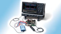
An oscilloscope and a device under test (DUT) constitute a de-facto system. In it, the most overlooked element is the interface between the two: the oscilloscope’s probes. Test personnel simply grab and use probes. Rarely do these engineers consider the probe’s impact on measurements. However, probes are among the most critical elements of the signal chain in any test scenario.
Related Articles
- Today's Oscilloscopes Tackle Evolving Communications Standards
- Oscilloscopes Evolve From Center Instrument To The Only Instrument On Your Bench
- What's The Difference Between Real-Time And Sampling Oscilloscopes?
The ideal oscilloscope probe would make contact with the DUT and transmit its signal from the tip of the probe to the instrument’s input with perfect fidelity. It also would exhibit zero attenuation, infinite bandwidth, and linear phase characteristics at all frequencies. Unfortunately, this probe does not exist in the real world.
The DUT has its particular electrical characteristics for a given signal, which are what we want to measure. However, the probe itself is a circuit with its own electrical characteristics. When the probe tip meets the DUT, the probe suddenly becomes part of a larger circuit, and its characteristics combine with those of the object of interest in a way that affects the measurement results.
To make a measurement, the probe must “steal” some of the energy present in the DUT and transfer that energy to the oscilloscope’s inputs. For one thing, we introduce the probe’s input impedance into the circuit. To the DUT, the probe constitutes a load presenting resistance, capacitance, and inductance. This load on the circuit can change the signal’s shape and/or the behavior of the DUT.
This file type includes high resolution graphics and schematics when applicable.
How Probes Affect The DUT
Broadly speaking, there are three possible outcomes when a probe is connected to a circuit. In the best case, the oscilloscope accurately reproduces the signal on screen. However, the probe may alter the signal in a way that misleads us about what is present at the probing point. A worst-case outcome is that the operation of the DUT changes radically, causing a well-designed device or circuit to malfunction (or vice versa).
Probes are designed with high resistance at the point of contact in the hope of reducing the energy drawn from the circuit and, thus, reduce the loading. High input resistance is important but it only makes a difference at dc or at low frequency ac. At different frequencies, different characteristics of the probe gain importance (Fig. 1).
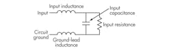
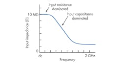
At dc or low frequencies, the high input resistance dominates the overall impedance. As frequency increases, the capacitance dominates the impedance and dramatically lowers the overall impedance. The result of the high probe capacitance then shows up in the signal shape seen on screen.
At 1 Hz, the impedance of a typical passive probe is 10 MΩ. At 1 MHz, that value decreases to 17.4 kΩ. At 100 MHz, impedance is just 174 Ω. With such a sharp drop-off in overall impedance, it’s not surprising that the probe can have such a dramatic impact on what’s seen on screen.
There’s one more major piece to the puzzle of a probe’s impact on the DUT: inductance. In typical measurement scenarios, the scope user can’t just connect the probe tip to the DUT, except in the case of making floating measurements. The probe’s ground lead must be attached to earth ground, or as close as you can get to it. All measurements are fundamentally differential in that there has to be some kind of reference point to measure a voltage. In general, that reference point is earth ground.
Thus, it’s important to be aware that any lead added to the probe tip or the ground wire adds inductance to the circuit. The inductance from leads can add overshoot and ringing to the signal seen on the oscilloscope’s display. Moreover, leads can serve as antennas and pick up electrical noise from the environment. That noise may or may not be present in the circuit you’re trying to measure. So, keep leads as short as possible to minimize these unwelcome inductance effects.
The probe’s lead length will present some amount of inductive loading to the input ground leads (Fig. 2). The ground lead is the primary return path for current that results from the input voltage acting with the probe’s input impedance. The ground lead’s and input lead’s inductances combine with the probe’s input capacitance to form a series LC network. That network’s impedance drops substantially at its resonant frequency. This effect, known as ground lead corruption, is the cause of ringing often seen after the leading edge of pulses.
How is it possible to alleviate ground lead corruption? One way is to raise the resonant frequency of the LC network by decreasing the inductance, the capacitance, or both. Realistically, because the input capacitance is already very low, the only option is to reduce the input inductance by using input and ground leads that are as short as possible.
Capacitive loading can be a difficult nut to crack, as it can affect rise time, bandwidth, and delay measurements. At high frequencies, capacitive loading can affect the amplitude and waveshape of measured signals.
Probe Types And Their Characteristics
Many kinds of oscilloscope probes are on the market with differing functions and electrical/physical characteristics. Some suit low-frequency applications. Others function well at high frequencies or high voltages. Here are some of the salient characteristics of common probe types with some tips on which ones serve best in given circumstances:
Passive probe:
• Standard oscilloscope probe supplied by all scope manufacturers
• No active devices, only passive parts
• Physically and electrically robust; handles hundreds of volts
• Maximum bandwidth is 500 MHz for most passive probes, but probe loading becomes an issue at higher frequencies
Active probe:
• Typically an optional probe powered by the oscilloscope
• Based on an active device such as a transistor or FET
• Not as robust as a passive probe but has much wider bandwidths and much lower capacitance
• The ideal probe for high-frequency measurements
Differential probe:
• Measures the difference between two signals when there is no ground reference
• Comes in two flavors: high voltage for floating measurements in a power supply, lighting ballast, motor drive, etc., and high bandwidth for differential serial data streams
Current probe:
• Active device that measures the current in a signal rather than the voltage
• Three main types: transformer based; Hall effect devices; or combination transformer/Hall effect
• Most modern clamp-on current probes are combination transformer/Hall effect types
Passive Probes: One Size Fits All
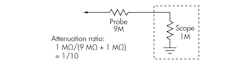
A passive probe essentially constitutes an attenuator circuit due to the probe impedance and the oscilloscope’s impedance. If the coupling of the probe to the oscilloscope is set incorrectly, the result can be a signal that is over-attenuated. Fortunately, modern passive probes automatically set the correct coupling and attenuation factor.
High-impedance and low-capacitance (or low-impedance) passive probes also are on the market. High-impedance (Hi-Z) passive probes are the most commonly used oscilloscope probes and offer attenuation factors of 10:1 (X10) and/or 100:1 (X100), a typical maximum input voltage of 600 V, and rated bandwidths of up to about 500 MHz. But be wary at bandwidths above 50 MHz. Hi-Z probes present an appreciable amount of capacitive loading at high frequencies.
Thus, Hi-Z passive probes best suit general-purpose applications at 50 MHz or less. Because they use only passive components, they tend to be robust mechanically and electrically. They’ll also provide a wide dynamic range, with the low end of the amplitude range limited by the probe’s attenuation factor and the oscilloscope’s vertical sensitivity.
Low-impedance (Low-Z) passive probes generally provide a 10:1 attenuation factor into the oscilloscope’s 50-Ω input termination. Where the high impedance probe uses capacitive compensation to provide flat frequency response with minimum capacitive loading, the low capacitance probe uses transmission line techniques to achieve extremely wide bandwidth with very low capacitance.
Low-Z passive probes are best suited for wide-bandwidth or fast-transient measurements in circuits that can drive 50-Ω impedances. In such cases, they offer excellent frequency response. And, unlike Hi-Z probes, low-Z probes do not require compensation to match the oscilloscope’s input impedance.
To provide impedance matching at the oscilloscope’s signal inputs, Hi-Z passive probes always have an adjustment trimmer capacitor located at the connector end. The trimmer implements a simple RC compensation scheme that matches the time constant of the RC circuit in the probe to the time constant of the probe input resistance and shunt capacitance.
The adjustment compensates for the capacitive load of the oscilloscope’s input. It forms a high-pass path to compensate for the low-pass nature of the oscilloscope input. As a result, the probe and oscilloscope combination becomes an all-pass filter. All oscilloscopes have a cal (short for calibration) output that provides a clean square wave for adjustment and compensation of passive probes. Adjusting the trimmer capacitor tunes the probe for that oscilloscope. Just turn the trimmer until a proper pulse shape appears on the display.
Active Probes: Higher Impedances
Passive probes are basic, general-purpose devices. Active probes often suit more specialized applications. The main difference between the types is that the passive probe contains no active components while the active probe includes an amplifier near the probe tip, most commonly based on a transistor or FET. Such probes typically provide higher overall impedance than passive types, presenting high resistance to dc voltages and low-frequency signals and low capacitance to high-frequency signals.
Active probes have high resistance at the probe tip but terminate into the 50-Ω input of the oscilloscope. When considering active versus passive probes, probe impedance is an important factor. Passive probes provide the highest impedance below frequencies of 20 kHz. Their high input capacitance causes circuit loading at high frequencies or with low-frequency signals containing high-frequency content.
Meanwhile, active FET probes provide high impedance from dc to 20 kHz, maintaining that impedance out to about 1.5 GHz (typical) thanks to their low capacitance (Fig. 3). FET probes, then, are truly general-purpose probes at nearly all frequencies. Their low capacitive loading makes them usable on high-impedance circuits that would suffer severely from loading with passive probes.
Knowing whether to use a passive or active probe in a given measurement scenario prevents incorrect results or damage to the probe. Passive probes are an excellent choice for low-frequency measurements, especially if high voltages may be encountered. Active FET probes are better suited for measurements requiring high bandwidths. They also are a great general-purpose choice for all frequencies out to the multi-gigahertz range, but watch out for higher voltages, which could damage the probe amplifier.
Differential Probes: When “Ground” Is Relative
General-purpose single-ended probes (whether active or passive) can only accurately measure “ground-referenced” voltages. However, some measurements require probing test points with reference to each other, whether one of them is true earth ground or not. One example is the VDS of a FET in a power supply. Another is a serial-data link, when it is necessary to probe the positive and negative data lines of a differential signal.
Here is where differential probes come into play. Among the most common are high-bandwidth types, high-voltage types, and those with differential amplifiers offering a high common-mode rejection ratio (see “About Common-Mode Rejection”).
High-bandwidth differential probes best suit applications such as probing differential serial-data lines. To function effectively, high-bandwidth probes must deliver high dynamic range at the higher bandwidths and a large offset capability. Another must for such probes is extremely low probe noise and impedance characteristics that minimize loading.
High-voltage differential probes typically handle common-mode voltages up to 1-kVRMS and 1.4-kV peak differential voltages, such as Teledyne LeCroy’s ADP305 (Fig. 4). Such probes suit troubleshooting of low-frequency power electronics in cases where ground is elevated or the location of true earth ground is unknown. When looking at high-voltage differential probes (or any high-voltage probes, for that matter), be mindful of safety ratings.
David Maliniak is a technical communications marketing specialist at Teledyne LeCroy. He is a 30-year veteran of the EOEM press and a former technical editor with Electronic Design. He has a BA in journalism from New York University.
About the Author

David Maliniak
MWRF Executive Editor
Comment About the Article
To join the conversation, and become an exclusive member of Electronic Design, create an account today!

Leaders relevant to this article: