Warning: Your DMM is Discharging Your Battery Cell
The most common measurement made on a lithium-ion battery cell is the voltage. Therefore, a voltmeter or digital multimeter (DMM) is often used in the R&D lab or on the manufacturing floor. Engineers and scientists will make voltage measurements and rarely think about how the measurement affects the battery cell. In fact, each time you connect the DMM to the cell, the DMM pulls a small amount of current out of the cell and continues to do so for the entire time the DMM is connected to the cell’s electrode contacts.
If you’re trying to measure the cell’s open circuit voltage (OCV), then by definition, you’re trying to measure the cell’s voltage when no current is flowing out of the cell. To measure the OCV, you connect the DMM in voltage measurement mode, which completes a circuit from cell+ to cell- and you’re no longer measuring the OCV. Now, this may sound like a matter of semantics, but if there’s concern you may be drawing current from the cell when you aren’t trying to do that, then these nuances matter.
If the DMM in voltage measurement mode is presenting an open circuit to the cell, then the DMM would need to have infinite impedance such that no current would flow. Of course, it does have some finite impedance, so we’re assuming the impedance is high enough that effectively no current flows when the DMM is connected. Therefore, for this assumption to be a good assumption, the DMM must have very high impedance such that very little current flows.
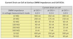
DMMs in voltage measurement mode do have high impedances, typically from MΩ to GΩ. The table below uses Ohm’s Law to calculate how much current will flow based on the impedance of the DMM, where current drain on cell = OCV/DMM impedance.
Observing the table, clearly these currents are quite small. If a DMM is connected for a few seconds or even a few minutes to make a measurement, this total capacity drain will be, at most, a few microamp-seconds and is thus insignificant.
However, when the DMM in voltage measurement mode has 10-MΩ impedance, the current drain approaches a microampere. In this case, if the DMM is connected for hours or days or weeks, say to monitor voltage drop during aging, this unwanted current drain caused by the DMM could have a noticeable effect on the cell. If the cells are of very low capacity, such as a specialty cell for a hearing aid, this could alter the cell’s state of charge (SoC) and induce a measurable change in OCV. Having the DMM be the cause of the OCV drop isn’t desirable when you’re trying to monitor OCV versus time during aging!
Voltage Measurement Mode
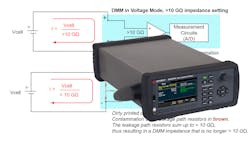
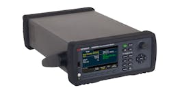
Let’s now take a closer look at the DMM in voltage measurement mode. Some DMMs have a user setting for the impedance of the DMM. For example, the DMM in the Keysight DAQ970A Data Acquisition System (Fig. 1) has a user-selectable impedance setting of 10 MΩ or >10 GΩ.
When in 10-MΩ input mode (Fig. 2), a 10-MΩ resistor is switched in to give the proper impedance. When in >10 GΩ mode, there’s no resistor and the impedance is the highest possible based on impedances of the circuit board and the circuits. So, while the >10 GΩ is desirable due to the lower current draw, the impedance is much less precisely controlled and will change (go down) with instrument age and conditions.
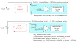
The changes in DMM impedance come from leakage currents caused by dirt, dust, and other contaminants on the DMM’s printed circuit boards (PCBs). The environmentally deposited particles, called leakage path resistors, act like real resistors added to the circuit board that result in an uncontrolled and undesirable path for current to flow (Fig. 3). While clean boards in a new instrument will allow the instrument to have an impedance of >10 GΩ, the impedance of the boards will drop over time as they get increasingly dirty. This drives the >10-GΩ mode to move down in impedance, causing current drain on the cell to go up, albeit from picoamperes to microamperes.
When using a DMM with GΩ impedance, it’s also important to take care to connect the DMM with wiring that maintains the high impedance between cell+ and cell-. Polytetrafluoroethylene (PFTE) Thin Wall PVC (TWP) wiring must be used to maintain GΩ impedance levels. Also, it’s important to remove any flux residue at the interconnections.
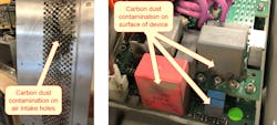
Parting thought: Since this is a discussion about using DMMs to measure lithium-ion cells, it’s necessary to point out that a potential source of environmentally deposited particles is found in a cell fabrication environment—namely, carbon dust. With electrodes made from graphite or other carbon materials, fine particulate carbon dust can be in the air.
It’s in the best interest of the cell maker to prevent this kind of contamination as it can be messy, hazardous to breathe, and may cause electrical shorts. And even if the density of the particles isn’t enough to conduct high current, in low density, the carbon dust will still contaminate the surface of a DMM’s PCBs and change the DMM’s impedance. With contamination, impedances of GΩ will be impossible. With enough contamination, even regular operation of the DMM may be disrupted (Fig. 4).
Bob Zollo is the Solution Architect for Battery Testing, Electronic Industrial Solutions Group, at Keysight Technologies.
