
Single-shaker vibration test systems have been used for many years to explore a test item’s resonances. Swept sine testing applies only one frequency at a time so resonances are excited separately. In contrast, random vibration testing simultaneously stimulates the test item with many frequencies, causing multiple resonances to be excited. Random vibration is a more realistic test, and because it drives the test item at several frequencies at the same time, it is faster than swept sine testing.
Nevertheless, a single shaker can only excite the test item in one direction. Many studies have concluded that adding together the results of separate tests in each of three orthogonal directions is not always equivalent to simultaneously applying vibration in all three axes. The two situations do produce the same results if the test item behaves linearly. If it doesn’t, sequential uniaxis testing will fail to stimulate the cross-axis modes that are excited when two or more axes are simultaneously driven.
Sometimes the test item is mounted on an angled fixture that allows a single shaker to simultaneously drive two or three axes. For a rectangular item, for example a simple PCB, it may make sense to assign X and Y axes parallel to the length and width of the board if most of the components are mounted in these directions. However, when an angled fixture is used with a single shaker, the vibration in the excited axes will be in phase, which may not be realistic.
A recent paper1 describes a test that addressed single-shaker constraints: “… [the paper] examines how well two uniaxial test methods approximate the damage incurred under true multiaxial vibration using a novel simultaneous multiaxial base excitation electrodynamic (ED) shaker. Nonlinearities due to high-amplitude vibratory environment and multiaxial excitation are discussed….”
The test item was a small four-layer PCB with six cylindrical ferrite-core axial-lead inductors mounted on it. Each inductor weighed approximately 23g and measured 21 mm in diameter and 23 mm in height. The lead wires were soldered to the PCB with a 2-mm stand-off distance. Because the leads for any one inductor had the same X coordinate—the mounting holes were in line in the Y direction—excitation was applied along only the X and Z axes.
Uniaxial testing in the X direction stimulated a resonance at approximately 72 Hz with the component rocking back and forth in the X direction. Separately driving the test setup in the Z direction also excited this resonance but with significantly lower transmissibility. In contrast, simultaneously exciting both axes yielded a damage accumulation rate that was much higher than the sum of the results from the uniaxial tests.
The authors comment, “The magnitude of the durability difference between sequential uniaxial tests and simultaneous multiple degree of freedom (MDOF) tests depends on the amount of nonlinear cross-axis interactions.” And, in the paper’s conclusion, they further state that, “… linear superposition is incapable of capturing nonlinear behavior.”
Hardware
The equipment used to simultaneously excite MDOF can be separated into two generic types—orthogonal and hexapod. The MTS Systems Model 323 system being used to test automotive components in Figure 1 can provide true 6DOF vibration. As described in the company’s MAST (multiaxial simulation table) brochure, “Model 323 systems include a stiff, resonance-free vibration table that supports the test specimen, plus longitudinal, lateral, and vertical actuators. The standard configuration provides either 4DOF or 6DOF motion…. To accomplish this, the system uses three vertical actuators that provide vertical (heave), pitch, and roll motions, plus three horizontal actuators that provide lateral, yaw, and longitudinal motions.”
Courtesy of MTS Systems Corp.
Hexapods, in contrast, use six actuators to support a movable table above a stationary base plate. As shown in Figure 2, the actuators are mounted at an angle so that when driven in various combinations, they can deliver 6DOF motion. For many test applications, either form of machine could be used. However, because all six of a hexapod’s actuators provide vertical force, this structure is very stiff in that direction and may support a higher load than a similar orthogonal machine. On the other hand, orthogonal systems may provide higher bandwidth.
Courtesy of Moog CSA Engineering
With actuators optimized to have a very long stroke, a hexapod remains relatively compact but can address applications that require a large amount of motion, such as flight and driving simulators.
Moog’s hexapods intended for use in vibration testing, such as the type HX-M350 in Figure 2, are called simulation tables and are available in both electrical and hydraulic versions. The company’s website lists “noise and vibration testing; component and subsystem structural performance; ride quality assessment of seat systems, cockpit modules, and entire vehicles; and dynamic functional testing on fuel tanks, antennae, and turrets” as applications.
Team, today part of the Noise and Vibration Technologies Group, was working on a different type of orthogonal 6DOF concept before March, 2005, the date of the company’s patent US 6,860,152, “High Frequency Multiple Degree of Freedom Vibration Test Machine.” The configuration described in the patent used only six actuators but opposed the horizontal shakers with fixed preload pistons. For example, two actuators were used in the X direction driving opposite sides of the test platform. Each was opposed by a preload piston, so it’s easy to see how the same polarity drive to both actuators would produce rotation. Driving them with opposite polarity causes lateral motion.
The company’s small Tensor 900 machine was developed at about that time and used 12 ED actuators—four in two opposing pairs in both X and Y rather than having separate preload pistons. In the Z direction, a preload device is necessary to oppose the actuators located under each corner of the table. As the datasheet states, the unit supports a bandwidth from 10 Hz to 5 kHz with a 200-lbf force rating for both sine and random excitation. The 8- x 8-inch table supports up to a 9-lb load, and the machine can impart 10g acceleration.
The datasheet explains an interesting aspect of such a high-bandwidth 6DOF machine: “The unique arrangement of shakers around and under the moving table facilitates dynamic control of mode shapes resulting in better control. This feature offers unparalleled control precision, taking advantage of the sophisticated algorithms that form the basis of contemporary test controller software.” With 6DOF control, the machine is capable of counteracting multidimensional vibration modes—something that single-shaker vibration testing cannot do.
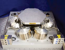
Team’s much larger Tensor 18kN machine (Figure 3), launched in 2012, has a 30- x 30-inch table capable of supporting a 300-lb payload. Bandwidth is 5 Hz to 2,000 Hz, and the unit provides up to 5g rms acceleration. According to the datasheet, “Twelve integrated ED shakers provide 4,800 lbf in each axis.”
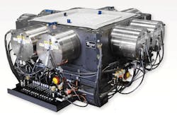
Courtesy of Team
A feature of all multi-DOF machines is a very stiff bearing design. Team included hydrostatic pad bearings when describing the 18kN system in a 2013 article.2 MTS uses hydrostatic bearings in its hexapod machines and on the company’s website describes their operation as ultra-stiff and low-friction with zero backlash.
IMV also provides a wide selection of vibration testing equipment. Many of the company’s compact three-axis machines feature a patented integrated cross coupling unit, which, as shown in Figure 4 and explained on the company’s website, “… contains all the [hydrostatic] bearings necessary for free motion in three orthogonal axes in one unit.” Claimed advantages include lower weight as well as smaller size.
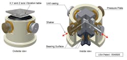
Courtesy of IMV
Figure 5 shows a very large type TS-9600-40L 6DOF IMV railroad vehicle test system that uses an alternative coupling method in which, according to the website, “Each vibration generator is connected to the vibration table by a force rod that transmits the excitation force to the table. Spherical bearings are installed at each end of the rod to enable the vibration table to move freely in any direction.” This system provides a 51-mm maximum displacement and a 1-Hz to 150-Hz frequency range. Two actuators are used in both the X and Y directions with an additional six in the Z direction under the 4-m x 3.5-m table.
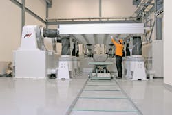
Courtesy of IMV
Control ED or hydraulic
The SignalStar Matrix vibration controller from Data Physics, part of the Noise and Vibration Technologies Group, provides from 40 to 1,024 input channels, which can all be used in any combination of control and limit channels. From two to 16 shakers can be controlled in multishaker applications. These include multishaker single-axis as well as multishaker multiaxis both for MDOF single table tests and in cases where multiple shakers are directly attached to the unit under test.
Multishaker single-axis operation may be required for very long test items, such as a space rocket. It’s important that a controller provide precise amplitude and phase matching for all the shakers when the objective is to simultaneously drive all parts of the structure with the same signal. Alternatively, a three-shaker setup can be controlled to impart a rocking motion with the two end shakers driven out of phase and the central shaker acting as a pivot. Of course, many other combinations are possible.
As the company’s website states, “The real vibration environment for a structure is complex with multiple excitation sources. … [SignalStar] Matrix uses continuous control to adapt to the dynamics of the system under test. Compensating the cross coupled dynamic responses of the multiple inputs simultaneously yields high control accuracy. Matrix offers independent reference definition of each control point with defined phase and coherence between control points. Matrix offers control capability for all multishaker scenarios from automotive durability testing to advanced spacecraft testing.”
A Data Physics white paper3 discusses both time- and frequency-domain approaches to time waveform replication—the process of testing an item by replaying previously recorded actual vibration data. The paper gives an idea of the mathematics involved when dealing with a large number of accelerometer feedback signals as well as several ED shakers:
“One of the problems in [multi-]DOF time waveform replication is the inversion of the system transfer function matrix [that is] required for the convolution with the reference time history matrix. When this matrix is square and its determinant is non-zero (at every frequency), then many techniques can be used for inversion. When the matrix is rectangular (this is the general case), then singular value decomposition (SVD) is typically used to factor the matrix into the product of three matrices, H=U*S*VT and determine the Moore-Penrose pseudo inverse. This has the additional benefit that it automatically yields the true inverse if such a matrix exists.”
A recent article4 discusses some of the control considerations that accompany so-called overactuated 6DOF configurations in which there are more actuators than degrees of freedom. The authors state, “Square control [equal number of actuators and DOF] does not assume rigid-body motion and can be capable of controlling the plate’s motion much more effectively. However, care needs to be taken when the actuator configuration is over-actuated and the 6DOF system’s platform is very stiff within the frequency range of interest.” One benefit of square control is its capability to “unbend” at least some of the platform’s modal reactions because it does not assume a rigid platform. The warning about over-actuated systems is given because the input/output rectangular matrix transformations needed in this case may assume a rigid platform.
Continuous control also has signal processing implications. Reference 3 further explains, “An FFT is used to convert the reference time histories to the frequency domain, and this is multiplied by the inverse of the [frequency response function] FRF matrix, H-1, to produce the drive signal, D(f) in the frequency domain. An inverse FFT is used to create the drive time history frame, d(t). This is done for each frame in the reference time history.… This FRF-based control technique can be extended to be used for real-time correction of the drive signals by measuring and updating the FRF matrix during the test phase. This allows continuous convolution of the time history signals with the inverse of the system dynamic response.”
Spectral Dynamics also provides a vibration controller that accommodates large test requirements through scalability. The Jaguar system includes several models ranging in capacity from eight to 18 inputs for the smallest chassis to a total of 588 for a system with six synchronized 98-channel chassis. The standard input sampling rate is 51.2 kS/s with an available 102.4-kS/s advanced option.
The company uses the MIMO term to describe applications involving several inputs and up to 16 outputs. Outputs are sampled at 204,800 S/s and have a dynamic range >90 dB. Information on the website states, “You may change the control scheme for the control loop among square control, rectangular control, and hybrid control with null drives.” Here, rectangular refers to having more control inputs than actuator outputs and implies a type of averaging among the control inputs. “Hybrid control is used with input/output transformations to force particular drives to zero energy (null drive) below a selected frequency,” according to the website. Basically, the hybrid control mode “… supports a transition between the square and rectangular control methods.”
Moog provides two types of large system vibration controllers—one for aerospace testing with up to 500 channels and one for automotive with up to 32. The aerospace controller addresses the servo channels with the company’s force or displacement control loop technology with a 2.5-kHz sample rate. Inputs and outputs are digitized to 16-bits resolution. The automotive controller drives applications such as four- to eight-post test systems, 6DOF suspension test rigs or simulation tables, and durability and fatigue tests. A choice of force, position, or acceleration feedback is supported together with a signal-generation frequency range from 0.01 Hz to 500 Hz. Both systems can be used with any type of hydraulic, electric, or pneumatic actuator.
Hydraulic
The FlexTest controllers from MTS are used with the company’s hydraulic MAST test systems and, according to the FlexTest brochure, “… provide high-speed closed-loop control, function generation, transducer conditioning, and data acquisition…. The controllers all use the same Series 494 hardware modules … including centralized processors which can be easily upgraded in the field. Additional test resource boards can be added. These capabilities help you to cost-effectively expand your controller capacity and/or extend the productive life of your controller investment.”
Among the compensation techniques supported by FlexTest controllers is adaptive inverse control (AIC), which, the brochure explains, “… can be applied to any waveform, including random profiles or remote parameter control time history files in linear systems…. With AIC, the command is adjusted in real time so the achieved response matches a target signal.”
The maximum drive frequency is 600 Hz, which applies to systems with one or two control channels that are updated at a 6,144-Hz rate. Multiplexing reduces the update rate in higher channel-count systems. For example, a very large system with more than 32 control channels samples at a 1,024-Hz rate. Following the company’s recommendation that the test frequency not exceed 10% of the update rate results in a 102.4-Hz upper test frequency for such a system.
Summary
There’s no question that multiaxial testing can be more realistic than a succession of uniaxial tests. However, hexapods and orthogonal 6DOF machines are more complex and expensive than a traditional single-axis shaker, and so are the controllers. Nevertheless, in the hands of an experienced test engineer, 6DOF testing can disclose vibration modes that are completely missed when testing one axis at a time.
References
- Ernst, M., et al, “Comparison of Electronic Component Durability
Under Uniaxial and Multiaxial Random Vibrations,” Journal of Electronic Packaging, March 2015, Vol. 137. - Hoksbergen, J., “Bringing Broadband 6-DOF Field Vibration Environments into the Lab—Tensor 18kN Vibration Test System,” Sound & Vibration, March 2013.
- Reilly, T., Time Domain and Frequency Domain Techniques For
Multi Shaker Time Waveform Replication, Data Physics, White Paper, October, 2013. - Ayres, R., et al, “Controlling 6-DOF Systems with Multiple Exciters,”
Sound & Vibration, October 2013, pp. 6-11.
For more Information
About the Author

Tom Lecklider
Comment About the Article
To join the conversation, and become an exclusive member of Electronic Design, create an account today!

Leaders relevant to this article: