Maintain Signal Integrity From Bus To Scope At 30 GHz And Beyond
With serial data rates continuing to climb, minimizing the effect of the measurement system’s internal noise on the signal is increasingly important. As output voltages shrink to boost speeds, the margin between pass and fail has shrunk to the point where noise from the signal and the measurement system can combine to close the eye.
Related Articles
- What's The Difference Between Signal Integrity And Power Integrity?
- Integrate Your Signals Before Digitizing Them
- Bill Laumeister Discusses Selecting A Solid Ground & Eliminating Noise Power
One of the most important elements in ensuring accurate measurements is the connection between the signal access point and the oscilloscope. This connection needs to be able to handle signals as fast as 30 GHz to ensure accurate results for compliance measurements, while adding very little noise. Fortunately, high-speed oscilloscope probes boost measurement accuracy at these higher data rates. They also help simplify what would otherwise be a daunting test and measurement challenge.
Signal Acquisition Requirements
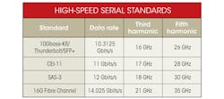
Data rates of third-generation serial bus standards continue to increase, moving the minimum bandwidth requirement for debugging many common buses beyond 16 GHz, and even 30 GHz (see the table). To ensure accuracy, standards bodies typically specify the use of an oscilloscope with a bandwidth several times more than the fundamental frequency of the serial signal.Support for differential, single-ended, and common-mode measurements is equally important in oscilloscopes and probes.
Nearly all high-speed data buses use transmission lines that are differential pairs, which are used for upstream or downstream communication. They are also used as lanes if the bus uses multiple transmit and receive lanes. Acquiring and measuring these differential signals with a high common-mode rejection ratio (CMRR) requires an oscilloscope probe with a differential amplifier input stage. High CMRR is needed to reject signals common to both sides of a differential pair. The common-mode signals can show as distortion or added noise in the differential measurement.
Acquiring differential signals is critical, but measuring each side of a differential pair individually (single-ended) and the common-mode components of the signal is important as well. Many high-speed serial bus standards specify that compliance testing must verify that a bus meets specifications for differential, single-ended, and common-mode voltage outputs.
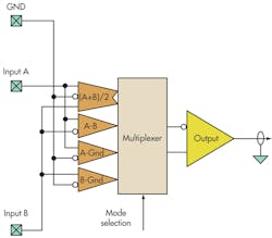
Differential probes with high bandwidths are readily available for measuring differential voltage levels. Measuring single-ended or common-mode voltages requires multiple probes or moving a single probe from point to point. A significant advance in usability is a new generation of probes that allow measurement of differential, single-ended, and common-mode voltage levels with a single connection to the device under test (DUT) using a single probe setup (Fig. 1).
Coaxial Connections
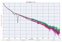
Connecting to high-speed buses often requires a controlled impedance board or fixture with coaxial connectors such as SMP or 2.92-mm/K-type connectors. An oscilloscope can be connected to the test fixture with coaxial cables with the appropriate connectors on each end. However, coaxial cables exhibit variable loss with respect to frequency (Fig. 2). This loss needs to be addressed.
In addition, any two coaxial cables are not identical in length and therefore have different propagation times. Differences even as small as a few picoseconds show as skew between differential signal pairs and can degrade the quality of the measured signal. Timing skew between cables needs to be measured and adjusted out for an accurate differential measurement.
A probe with coaxial input connectors eliminates the need for a separate set of coaxial cables. With the latest 30-GHz probes, the system response is calibrated in level (±1 dB) and skew (±2 ps) at the probe’s tip. This calibration eliminates the need to correct the measurement for loss or timing skew in a set of cables
To further enhance the measurement,the signal acquired at the probe tip can be corrected based upon S-parameter models of the probe and S-parameters of the oscilloscope system stored in each device. The model is automatically downloaded to the oscilloscope when the probe is connected.
These S-parameters are used to correct the frequency response for the measurement system including any loss or gain in the probe. Connecting to the test fixture directly with the probe reduces the distance between the signal output and the measurement system input and improves the fidelity of the measurement.
Coaxial connections also present challenges when making the various mode measurements required. If the two inputs are used for a differential measurement, making single-ended measurements means the engineer must ensure that the unused input is correctly terminated with 50 Ω. Measuring common-mode voltage is also more involved, requiring the test engineer to measure both sides of the differential pair (A and B), then inserting the two waveforms into:
Common-mode voltage = (A + B)/2 – the reference voltage (usually 0 V or ground)
The math function on an oscilloscope makes this calculation possible, but using waveform math adds time and complexity to the measurement. In contrast, the latest probes incorporate a switch matrix that allows the user to switch the routing of the signal’s differential pair.
Either side of the differential pair can be measured, as well as its differential and common-mode components. When making multiple differential, single-ended, and common-mode measurements, this eliminates the need to continually adjust and re-adjust the probe’s connection to the DUT. As an added convenience, the probe offers automatic probe tip identification, which ensures the correct digital signal processing filters are used.
System Noise
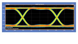
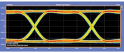
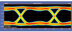
High-speed data signals achieve some of their speed increase by lowering the differential output voltages, making lower noise in the system and in the measurement system important. As the output voltages shrink, the margin between pass and fail gets smaller. An eye diagram measurement of a 12-Gbit/s serial signal illustrates how noise from the signal and the measurement system can combine to close the eye (Figures 3 and 4).
Measuring these lower voltage swings requires a probe and oscilloscope with a high signal-to-noise ratio (SNR) to minimize the effect of the measurement system’s internal noise on the signal. The latest probes and high-performance oscilloscopes together provide a system noise specification of less than 1 mVRMS. Previous probe and oscilloscope combinations can have as much as three times as much noise.
In addition, it’s important to keep the cable length from the DUT to the probe or oscilloscope as short as possible to minimize added noise. Locating the probe’s differential amplifier close to the DUT reduces the noise.
In addition to a high SNR, high sensitivity is desirable. Often access to the signal under test is at the end of a backplane or a compliance load board channel. The lower the serial signals’ amplitude, the more sensitive the probe and oscilloscope need to be. High-performance oscilloscopes and probes offer high sensitivity at 3.48 mV/div at 30-GHz bandwidth compared to more typical sensitivities of 10 mV/div or higher.
Probe Modeling
Design and implementation of serial data links often require many hours of simulation and modeling. Once hardware implementation begins, the serial links often require pre-emphasis/de-emphasis at the transmitter and equalization at the receiver. Engineers may wonder how the system will react when a probe is attached to their finely tuned link. As such, it is important to ensure that measurements reflect the true operation of the serial bus, with any effects of the probe removed.
One the more innovative features now appearing in higher-speed probes is the ability to store S-parameter models directly in the probe. These models can then be read by the oscilloscope’s software when the probe is attached to the scope. The oscilloscope then removes the effects of the probe from the measured signal and gives the engineer a view of the signal as it appears at the TX output or RX input.
Low-Noise Probes
As data communications standards move to higher and higher speeds, measurement systems must combine high bandwidth with low noise and high sensitivity. In addition to higher-bandwidth oscilloscopes and signal generators, engineers must consider the connection between the DUT and the oscilloscope’s input. Many serial standards also require differential, single-ended, and common-mode measurements.
While coaxial cables can be used for making the connection, this approach considerably burdens the engineer to measure and remove channel effects and to move connections around to make the different measurements. New high-bandwidth probes with coaxial inputs offer up to 33-GHz bandwidth performance for acquiring today’s high-speed serial bus signals with minimal added noise and smaller than 1X attenuation. They also provide the ability to measure differential, single-ended, and common-mode signals without changing physical connections.
This file type includes high resolution graphics and schematics when applicable.
Kevin Cassidy is a marketing manager and product planner for Tektronix high-performance probes. He has a BSEE from the USAF Academy and more than 15 years of experience in the test and measurement industry. He can be reached at [email protected].
About the Author
Kevin Cassidy
Marketing Manager and Product Planner
Kevin Cassidy is a marketing manager and product planner for Tektronix high-performance probes. He has a BSEE from the USAF Academy and more than 15 years of experience in the test and measurement industry. He can be reached at [email protected].
