Implantable Blood-Flow Sensor is Wireless, Battery-Free, and Biodegradable

>> Website Resources
.. >> Library: TechXchange
.. .. >> TechXchange: Power Management
.. .. .. >> Topic: Energy Harvesting
One of the metrics needed to monitor the success of blood-vessel surgery is blood flow and pressure through the repaired vessel, but measuring that parameter brings many obvious challenges. A team of researchers at Stanford University addressed the problem by developing a prototype tiny sensor plus a wireless RF link that’s biodegradable, battery-free, and doesn’t need to be removed—its output can be interpreted to warn if there’s a blockage. The sensor uses inductive coupling, has minimal hysteresis, fast response times, excellent cycling stability, is highly robust, is easily mounted, and the fact that it needn’t be removed reduces the risk of further vessel trauma (Fig. 1).
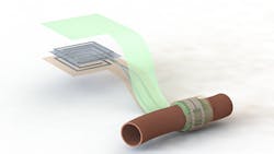
1. Artist’s depiction of the biodegradable pressure sensor wrapped around a blood vessel with the antenna off to the side (layers separated to show details of the antenna’s structure). (Source: Levent Beker via Stanford University)
The device combines a capacitive-based transducer with a self-powered, frequency-shifted RF link. The basic sensing structure is a multilayer “wrap” of an outer conductive layer that has a PGA (polyglycolic acid) inner layer with “micro pyramids” (Fig. 2). The wireless frequency ranges from about 700 to 725 MHz as the effective capacitance shifts from 2.2 pF to 1.6 pF in response to blood-vessel expansion and relaxation. A reader held outside the skin “pings” the antenna attached to the sensor, similar to a wireless ID card reader, to capture to signal.
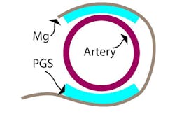
2. This cross-sectional schematic image of the sensor wrapped around an artery illustrates the basic concept of the capacitive sensor arrangement. (Source: Stanford University)
The antenna is laser cut from 50-µm-thick magnesium (Mg) foil (Fig. 3). The team evaluated several designs, and then chose the best-performing one based on simulation (Fig. 4). They also modeled the fringe-field performance of the capacitive sensor (Fig. 5).
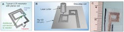
3. Wireless link design and fabrication: Typical LCR resonant circuit with planar coil; an additional fabrication step is needed to establish the electrical connection between the coil and the capacitor, while no additional connection is needed to “close” the circuit in the proposed method (A). The “additional connection” is a metal interconnect made of the same material as the coil and capacitor (or another material, e.g. tin in case of soldering). The conducting lines for electrical interconnects, capacitors and inductors are defined using a one-step fabrication process, with a computer-controlled laser cutter (B). Optical photo of a fabricated inductor (C).
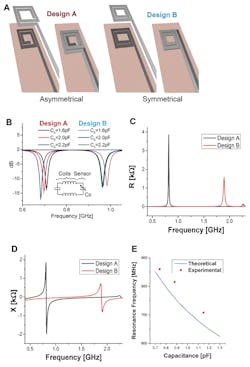
4. Wireless link design and optimization—two possible designs for the top and bottom coils were evaluated with 3D EM field simulations (CST simulation software). In design A, the top and bottom coils are asymmetrical (the top coil turns clockwise while the bottom coil turns counterclockwise, forming a quasi-closed large coil when they are superimposed on each other) (A). In design B, the top and bottom coils are symmetrical (same turn patterns when superimposed) (B). Simulated S11 return loss for whole system when the tag with sensor is coupled to a reader coil for both designs A and B. With similar sensor capacitance changes, the response shift for Design A is more linear. Electrical simulation results of Design A and B showing resistance (C) and reactance of Designs A and B at the sensing capacitance port with no coupled reader coil (D). Comparison of theoretically calculated resonance frequency (E).
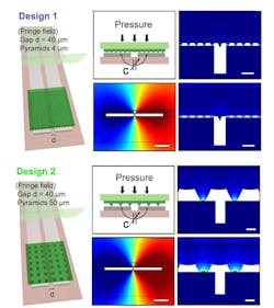
5. Two designs for the fringe-field capacitive sensor were evaluated with 2D finite element method (COMSOL simulation software). In Design 1 (left), the micro-structured, the elastomeric PGS layer has smaller pyramids (base 4 μm, height 2.8 μm), while in Design 2 (right), the PGS layer has larger pyramids (base 50 μm, height 35.3 μm). (Scale bar is 40 μm.) Multi-physics simulations included both mechanical and electrostatic models plus a moving mesh for evaluation of the mechanical deformation of the system under applied pressure, together with the corresponding capacitance change when mechanical deformation is applied.
Both testbench and in-vitro testing are critical elements of the evaluation and validation process. First-phase testing was done using a flexible tube with material characteristics similar to arteries. The assembly was wrapped around the tube and precise amounts of air pressure was pumped (Fig. 6). Subsequent tests implanted the assembly in a subject rat (who was OK after the tests!) (Fig. 7).
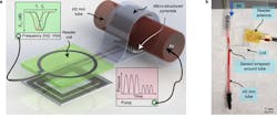
6. Shown is a schematic diagram of the arrangement of the test fixture and unit under test (a), and the basic sensor assembly and tube used for simulating blood vessel (b).
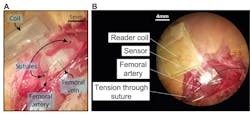
7. Fixation of the sensor during surgery, shown with a photograph of the implanted sensor after suturing the sensor to femoral artery (A), and the occlusion test design where two sutures are wrapped around the femoral artery distal and proximal to the sensor (B).
Their paper “Biodegradable and flexible arterial-pulse sensor for the wireless monitoring of blood flow,” published in Nature Biomedical Engineering, provides basic biomedical and device details. In addition, the Supplementary Information paper offers more details on the engineering of sensor, antenna, RF, and mechanical design, including the options evaluated, fabrication details, testing arrangements, and performance. Some in-vivo videos also are posted.
>> Website Resources
.. >> Library: TechXchange
.. .. >> TechXchange: Power Management
.. .. .. >> Topic: Energy Harvesting

About the Author

Bill Schweber
Contributing Editor
Bill Schweber is an electronics engineer who has written three textbooks on electronic communications systems, as well as hundreds of technical articles, opinion columns, and product features. In past roles, he worked as a technical website manager for multiple topic-specific sites for EE Times, as well as both the Executive Editor and Analog Editor at EDN.
At Analog Devices Inc., Bill was in marketing communications (public relations). As a result, he has been on both sides of the technical PR function, presenting company products, stories, and messages to the media and also as the recipient of these.
Prior to the MarCom role at Analog, Bill was associate editor of their respected technical journal and worked in their product marketing and applications engineering groups. Before those roles, he was at Instron Corp., doing hands-on analog- and power-circuit design and systems integration for materials-testing machine controls.
Bill has an MSEE (Univ. of Mass) and BSEE (Columbia Univ.), is a Registered Professional Engineer, and holds an Advanced Class amateur radio license. He has also planned, written, and presented online courses on a variety of engineering topics, including MOSFET basics, ADC selection, and driving LEDs.
Comment About the Article
To join the conversation, and become an exclusive member of Electronic Design, create an account today!

Leaders relevant to this article: